Hoverfly XY-8 Build, Rev4, Hoverfly

Bartman

Welcome to MultiRotorForums.com!!
well, i'm running full bore bringing it all together so it's going to be soon. yesterday was spent at the shop that does assembly of the camera mounts. we bonded the parts for Rev7 and it's lighter, strong, and being built with fewer parts so that's all good. assembly of the parts went well last night and it's balancing nicely with my T2i mounted to it. I've got to get my hands on a 5D to see how it fits before going ahead with more parts sets.

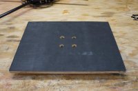
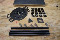
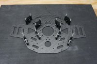
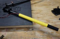
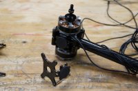
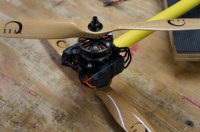
the frame parts got here on Wednesday but I only took a look at them last night. the first heli is partially assembled on the bench and once it is all checked for dimensions and clearances i'll start the second one and post photos.

it's extremely gratifying to see a lot of hard work take shape on my workbench. maybe if the weather clears out i'll be ready to fly by SUnday. this first build is getting a tried-but-true Rev6 camera mount so I might have some video from onboard as well.

thanks,
bart
 

SleepyC

www.AirHeadMedia.com
Sounds awesome. Can't wait to see some pics!
I'm in Illinois covering eFest, but I'd rather be playing with/building Heli's!
(I did bring my lil guy to at least get some aerial shots of eFEST)
 

Bartman

Welcome to MultiRotorForums.com!!
Moving right along, I took a few minutes the other night to make a building board. I've become clean-obsessed around these builds so the board allows me to keep the build area spotless and to move the whole shebang out of the way to do other things on the bench or to just give the area a good once-over with the vacuum.

View attachment 9526

Laying out the parts I've got the upper and lower frame plates, fasteners, motor and boom mounts, as well as the rubber pads to keep the batteries from sliding around.

View attachment 9527

The top frame plate goes on the board first with the fasteners sticking up, everything gets laid into place. I've got to make a wiring harness for it this afternoon and that will be installed before the lower frame plate goes on.
View attachment 9528


For this build I'm reversing my prior standard and putting the LED's on the back arms. I can fly nose-in (had to say that) but most of what I do is nose out or sideways which makes the rear arms a better place for the LED's to be as that is where I can see them more easily. I"m still awaiting the completion of a prototype LED controller with RC control options and multiple outputs. I'm disproportionately excited about that one detail for some reason. :)
View attachment 9529


Next up is the mounting and wiring of the motors.
 

Attachments

  • DSC06928.jpg
    DSC06928.jpg
    143.7 KB · Views: 441
  • DSC06936.jpg
    DSC06936.jpg
    148.8 KB · Views: 355
  • DSC06939.jpg
    DSC06939.jpg
    146.7 KB · Views: 340
  • DSC06940.jpg
    DSC06940.jpg
    141.7 KB · Views: 216

Bartman

Welcome to MultiRotorForums.com!!
The motor mounts are my own design and will be available when the shop opens. The arm is for mounting ESC's and there's a round pad to cushion the ESC against the plate. The mount in the picture fits the Tiger 2814 and 4008 motors. I'll also be making mounts for the Tiger MT3515 and Navigator series of motors. Putting the ESC by the motor makes sense for 6S powered heli's as the wiring to them can be thinner/lighter. It gets the ESC's in the airflow allowing them to perform at their specified amp ratings. There's a note in the directions stating the ratings are with a 5mph wind over the ESC's to provide cooling.

View attachment 9530

The frame plates have room for the orderly mounting of eight ESC's, including holes to secure wire harnesses to the frame plates. While I've been using power distribution boards up until now, I'm moving away from them to have bullet connectors between the power harness and individual ESC's and motor wires soldered directly to the ESC circuit boards.

If I have time I'll wire up a 4S powered Rev4 frame to show the layout scheme with the ESC's on the frame plates. I should have this 6S powered heli wired for power and the motors installed tomorrow afternoon.

Tonight's project will be to start configuring a website.

Regards,
Bart
 

Attachments

  • DSC06944.jpg
    DSC06944.jpg
    137 KB · Views: 357
Last edited by a moderator:

SleepyC

www.AirHeadMedia.com
Ohhh man.. I just saw what you did with the building board. You made it so you bolt down the bottom plate which in turn holds the boom block bolts in place so you can work without everything constantly falling all over the place. That is a great idea. OK.. that's three "DUH, why is this the first time I'm seeing this" ideas you have shown in this thread. The ESC/motor mounts, boom mount flanges and now the bolt down build table. Nice work.
 

BorisS

Drone Enthusiast
Bart, will you be selling your boom clamps ? and any chance of a 25mm version ?

thanks

Boris
 

Bartman

Welcome to MultiRotorForums.com!!
Ohhh man.. I just saw what you did with the building board. You made it so you bolt down the bottom plate which in turn holds the boom block bolts in place so you can work without everything constantly falling all over the place. That is a great idea. OK.. that's three "DUH, why is this the first time I'm seeing this" ideas you have shown in this thread. The ESC/motor mounts, boom mount flanges and now the bolt down build table. Nice work.

that was part of it as well, to be able to build it more quickly without having to hold 16 bolts in place simultaneously. It's actually being built upside-down and the holes allow the stand-offs for the Hoverfly PROto go down into the board.


@Boris, What makes you ask for 25mm specifically? The plan after the XY8 is completed and in production is to build a flat Okto that will use 7/8" (Roughly 22mm) booms for heavy lift AP/AV work and LIDAR. The flat Okto will get the same treatment that makes my XY8 more than just another frame kit.

Bartman
 

jcmonty

Member
Bart, you may want to look at Rusty's latest clamps. I think that they are 21.5mm. May be cheaper than making your own.
 

Bartman

Welcome to MultiRotorForums.com!!
hmmm, i'll look into that, thanks. the scheme with the flat 8 won't be that style of clamping block at the inner mounting points and, as a result, the frame plates will likely be G10 instead of carbon fiber. mush less expensive, no RF blocking, and plenty up for the job.

bart


Bartman

Welcome to MultiRotorForums.com!!
I"m not sure this is related to Chinese New Year but my little bag of screws took 4 days to get here from Chicago. With the screws here I was able to get a couple of motors mounted and wired to see how it all will work. I'm pretty happy with it except for my skinny zip-ties which will be replaced by stronger ones when they get here. There's only so much you can do with skinny zip ties from Home Depot.

I'll be away from this project for a few days so first flights are pushed to next week. Next Wed and Thurs are forecasted to be in the mid 30's with partly cloudy to sunny skies so that'll be the target I'm going to shoot for.

Here's a pic. It's tough as hell to cut nice long wires down to less than two inches!
View attachment 9595
 

Attachments

  • 1-DSC06945.jpg
    1-DSC06945.jpg
    111.4 KB · Views: 364

Bartman

Welcome to MultiRotorForums.com!!
EDIT: SEE POST #58 BELOW BEFORE TRYING THIS


another quick update from the shop. we spent a long weekend with the kids in Florida (tried to, red tide and cold weather sent us home early) so not much has been done the last few days. i'm waiting on a few last little pieces to bring it all together so i hoping to get what i need by the end of the day tomorrow. these first time builds sometimes leave me ordering small parts at the last minute.

anyway, i made a wiring harness tonight for the flight control, receiver, and LED's. we've discussed this approach in other threads, i think it was yeehawnow's idea to pull power through the balance taps. i took it a step further and pulled power with three different voltages using different combinations of cells from within the 6 cell pack. the reason for doing this is that the Hoverfly PRO cannot take straight 6 cell power so you've either got to install a regulator (BEC), use a separate 3 cell pack, or pull partial power from the packs as I"m trying to do. the receiver can only take 2 cell lipo power and the LED's need 4S power.

i've got power for the flight control (3 cell power) coming from cells 1, 2, and 3. power for the receiver (the 30A Tiger ESC's don't have BEC's so power for the receiver isn't coming from the ESC's as it normally would) is coming from cells 1 and 2. power for the LED's is coming from cells 3, 4, 5, and 6.

i figure in a 15 minute (maybe longer, we'll see) flight using TWO 6000mah 6S packs the motors will be pulling down the cells waaaaayyyy more than the FC, Rx, and LED's combined so the effect of them drawing unevenly will be negligible.

here's a pic. it's not my neatest work but i don't think i'll be soldering to the voltage monitor ever again. the next harness will tap into the wires an inch or so from the plug that will hold the voltage monitor. the monitor will eventually be fit into the dome so it can be read easily on the ground and so the low voltage horns can be heard.

as for the Hoverfly OSD, the screen will show 3 cell power which can be doubled in my head for 6S voltage or I can divide by three (in my head and only when PH is engaged :) ) to get single cell voltage.

View attachment 9747
 

Attachments

  • DSC06997.jpg
    DSC06997.jpg
    144 KB · Views: 213
Last edited by a moderator:

SMP

Member
Bart, any chance that XY8 might fit into IATA guidelines?? Skyjib at 47x47x14 (with gimbal disconnect) is simply too large to fly around internationally.
 

Bartman

Welcome to MultiRotorForums.com!!
do you mean carry-on guidelines? the proportions of the layout are very similar to but slightly bigger than a 22" rollerbag. what gear wold you be flying and what does it weigh? I could make a smaller one to fit a roller bag with removable landing gear and camera mount.
 

SMP

Member
That's basically the thought process. Intl flights are shrinking bag dimension limits faster than we can keep up with. Challenge as always is small frame/hvy gear. Unfortunately it must lift 5D2 with 28mmIS (approx 1000g) and 50mm 1.2 (approx 1600g). I think that's a product that could find a home in a lot of folks garages, er suitcase..

Will take a look at modding the Droid AD6 first but if we come up short it would be very good to chat.

Thx Bart!
 

kloner

Aerial DP
smp, bart is an international commercial pilot so he'd be a good person to talk about it with

I want to move my esc's like that, looks cleaner and less noise around the center of the bird. bet your fpv gear is easier to make better like this.
 

Bartman

Welcome to MultiRotorForums.com!!
smp, bart is an international commercial pilot so he'd be a good person to talk about it with

I want to move my esc's like that, looks cleaner and less noise around the center of the bird. bet your fpv gear is easier to make better like this.

THe motor mounts will be available separately in the shop. They'll be black anodized.

I'll look into making a heli that will fit into a roller bag. It's highly unlikely it would go in with the camera mount, props, and landing gear attached but if those pieces could be easily attached and detached then I don't think a 5D is entirely out of the question.

Bart
 

Bartman

Welcome to MultiRotorForums.com!!
Unforeseen common ground

This multi-rotor helicopter thing can get a little confusing at times. I wrote above about using different combinations of cells from within one 6 cell pack to power different things and it's given me a little bite on the arse. I failed to account for what I think must be a common ground in the Hoverfly PRO board between the power inputs and the receiver inputs. I suspect this common ground caused my partitioned power taps to short out or add up in ways different from what I intended. Such is life when you experiment and try new things. What got me was the power to the receiver, the receiver connections to the PRO board and the power inputs to the PRO board were all sharing a common ground network that must have made the wiring harness run amuck. I'll have to revisit this in the morning but as of now, it's back to the drawing board as I can't change the common grounds in the receiver power and channel output ports nor can I change the common grounds on the PRO board and the PRO's channel input ports. I can still partition power from the pack using the balance plug but the power outputs have to go to things that don't share a ground like the LED's and Rx or LED's and the PRO board. The Rx and PRO though is looking like a no-no. This has been an interesting evening.

Bart


Top