Building first drone and new to this

Old Man

Active Member
I'm not sure how those leds work. so I just plug it into the port on the receiver?

The LED's are likely12v, give or take a little, so using the receiver as the power source is not an option. Most receivers have voltage limits of between 4.3v and 8v, +/- a little so you can't use that. Ideally, your MW will use a 3s battery, where the voltage is close enough to directly tap as the power source using an additional lead from the PDB. If your MR uses a 2s battery system a small additional battery would have to be carried to power the LED's or other items requiring 12v power. If the MR uses voltage higher than what a 3s system provides the installation of a small BEC would be needed to regulate the voltage downwards from a higher to lower level.

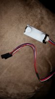
Since your LED's are already wired with JST connectors you have some power input plug options in front of you. Option 1 has all the JST connectors being removed in order to join the positive and negative wires together to make a single connection point. Meaning one group of negative wires and one group of positive wires, each ganged together in their own polarity with a single wire exiting each group to join up with a single connector. Option B is to make a wire connector set, where there are 4 outputs being provided from a single input source that connects to the primary power supply. Sort of like a "Y" but having two more legs on the "Y". Option C has you making a buss board that has a single "power in" but also having multiple pin outlets to plug different optional items into. Usually available space and weight end up making the decision as to which way an installation needs to be done. There's no on hard and fast rule that applies to this stuff, aside from a need to have some imagination and a reasonable amount of electrical assembly skills.
 

Hoki

Member
UHHHH WELL I HAD ORDERED A SLITTER CABLE THINGY WITH IT THAT HAS THE 4 CONNECTORS THAT PLUG INTO THE ONES ON THEM ALREADY AND IT HAS A BLACK CONNECTOR AT THE OTHER END THAT PLUGS INTO A 3 PIN THINGY.
 

Old Man

Active Member
and why are there no shells for the diy frames? like how the ones you buy in a store are all nice and smooth in a housing but the diys have to have all there insides exposed? I wanna make see about making a upper and lower shell out of syrofoam maybe just like crave it to shape or something, maybe paint it I donno. but I really feel the need to cover it. I don't feel right just being all naked plus it doesn't look at good.

Shells are like candy. We like it but it's not necessary. You can make a shell from just about anything. Inverted Tupperware containers are often popular for this application.
Best bet is just go back too the Shack.

Yep, tell them what you are doing and ask for product suggestions.


Hoki

Member
Ok i just got this stuff to help me telll me if its good stuff
 

Attachments

  • 20151230_154107.jpg
    20151230_154107.jpg
    118.6 KB · Views: 239


Hoki

Member
Shells are like candy. We like it but it's not necessary. You can make a shell from just about anything. Inverted Tupperware containers are often popular for this application.


Yep, tell them what you are doing and ask for product suggestions.
Yeah I'm not gonna make it look goofy with tupperware. I was thinking about making a mold and injecting some expanding foam inside it, maybe that would be easier.


Chalagi

Member
That exposed brass on the ends of those wires need to be covered with heat shrink tubing if not you will have a short at some point along the way. No exposed metal in that area.
 

Hoki

Member
Yeah I want to cover the whole thing but it shrinks I guess that when I connect it I'll make another little piece of shrink tube over that little area
 

Hoki

Member
Holy hot nuts. I need more plugs. Theres 1 last esc i cant do. I gonna order a bunch on amazon prime right now. They got them for 4 dollars for a 20 pack. Imma get 5 packs!
 

Hoki

Member
Well I try to cover up a little better this time around
 

Attachments

  • 20151230_210855.jpg
    20151230_210855.jpg
    60.9 KB · Views: 425

Hoki

Member
Ok well this as most as i can do. Still waiting for my motors but they might come in the next few days
 

Attachments

  • 20151230_222906.jpg
    20151230_222906.jpg
    102.3 KB · Views: 359


Hoki

Member
I don't know about this does this battery look too big? I'm not even sure if it's supposed to go here. If feels pretty heavy in the butt with the battery there
 

Attachments

  • 20151230_224409.jpg
    20151230_224409.jpg
    82 KB · Views: 273
  • 20151230_224349.jpg
    20151230_224349.jpg
    93.7 KB · Views: 272
  • 20151230_224924.jpg
    20151230_224924.jpg
    76.9 KB · Views: 225

JoeBob

Elevation via Flatulation
Exposed ends: once I'm sure that my props are rotating correctly, I'll paint the connections with Liquid Tape. That keeps them from separating in flight and prevents shorts. It peels off easily enough for repairs.
(Too much heat shrink tubing on the ends of your wires may keep your connectors from seating firmly, and compressed rubber will slowly push them apart.)

Battery positioning: Most battery holders are intended to offset the weight of a camera and gimbal on the front, so they tend to shift weight back. You can probably shift the battery position for now.
 

Hoki

Member
Is this how im supposed to mount th apm
 

Attachments

  • 20151231_152412.jpg
    20151231_152412.jpg
    115.2 KB · Views: 256
  • 20151231_152422.jpg
    20151231_152422.jpg
    108.7 KB · Views: 281

Hoki

Member
I ordered this buzzer and light thing but where do i plug it in
 

Attachments

  • 20151231_153947.jpg
    20151231_153947.jpg
    104.7 KB · Views: 279
  • 20151231_154000.jpg
    20151231_154000.jpg
    46.5 KB · Views: 262

Hoki

Member
So i connected the led buzzer tingy and i got it so the red led flashes with the status led on the apm and the blue flashes with the gps one and turns solid when it gets signal. It sooo freaking bright even with that white cover on it. I donno where to put this. I got the buzzer plugged in but i have no way to arm it to hear the tones and not sure i even got it plugged right for the buzzer. I do have the signal plugged in number 5 on the top pin but there was a red and black with that was a connection together so i out it on 5 as well with the red wire going to the middle and the black on the ground but not sure what the red wire is for...
 

Attachments

  • 20160101_170107.jpg
    20160101_170107.jpg
    89.3 KB · Views: 208

Hoki

Member
Oh and i soldered the escs to the pdb and im feeling weird now cause all this smoke was going in me
 

Attachments

  • 20160101_170119.jpg
    20160101_170119.jpg
    102.2 KB · Views: 319
  • 20160101_170126.jpg
    20160101_170126.jpg
    100.5 KB · Views: 231

Top