Mikrokopter MK power distribution board

Macsgrafs

Active Member
Hi guys,

I posted this question a few days ago, but for some strange reason the thread is missing!!!!!
so lets try again.....does anyone know if the pwoer tracks on the MK power distribution boards are continuous...do they go all the way around & without any breaks or is there a break in it at all? I have tried to find pictures of it, but nothing shows the track side.

Regards
Ross


Macsgrafs

Active Member
Hi Dave,

I have made my own power distribution board for my octo, it was cut from a blank PCB & I used a compass to mark out 2 complete rings, 1 for +Ve & the other for -V. I didnt know if to leave the rings complete or break them apart?

Ross
 

Droider

Drone Enthusiast
Hi Dave,

I have made my own power distribution board for my octo, it was cut from a blank PCB & I used a compass to mark out 2 complete rings, 1 for +Ve & the other for -V. I didnt know if to leave the rings complete or break them apart?

Ross


General consensus is dont join as it can create a magnetic thingymabob.. Check out posts by I think David scarbourgh

dave
 

Macsgrafs

Active Member
General consensus is dont join as it can create a magnetic thingymabob.. Check out posts by I think David scarbourgh

dave

I always thought, please correct me if I'm wrong, that magnetic thingymabob could only be generated by AC & not DC? Hence why ESC's produce AC from the DC to make the motor spin...but as I said, I could well be wrong? Now you see why I wanted to see if MK boards had a break or were complete?

Ross
PS But thanks for the input Dave, keep it up..between us we can get an answer ;)
 

Macsgrafs, a problem with current travelling along a piece of wire (or a board covered in copper) is that a magnetic field is 'created'. The strength of the mag. field is proportional to the level of current flowing...ie...a larger current will produce a bigger mag. field.
A smaller current will produce a smaller mag. field. DC just produces a mag. field in one direction only where AC produces a mag. field that continouosly changes relative to the frequency. The electronic devices may be effected by these mag.fields and how close they are to each other. AC can be additionally problematic if the current is travelling through a coil, and can induce additional (unwanted in this case) currents to flow.


Droider

Drone Enthusiast
Macsgrafs, a problem with current travelling along a piece of wire (or a board covered in copper) is that a magnetic field is 'created'. The strength of the mag. field is proportional to the level of current flowing...ie...a larger current will produce a bigger mag. field.
A smaller current will produce a smaller mag. field. DC just produces a mag. field in one direction only where AC produces a mag. field that continouosly changes relative to the frequency. The electronic devices may be effected by these mag.fields and how close they are to each other. AC can be additionally problematic if the current is travelling through a coil, and can induce additional (unwanted in this case) currents to flow.


Thanks Dave for clearing that up.. Is it a thingymabob then!?? :)

Dave
 

Dave,yes its called many things hence 'thingymajig'. Mag. fields and their effects are so unpredictable in these types of settings....the distribution board a centimetre further apart from where it currently sits, a single current carrying cable (conductor) routed differently, etc., etc. and lo ! the problem seems to disappear.


Macsgrafs, just be sure and careful on this...I use a distribution board that seems to be exactly as you have described yours but the 'circles of copper land pattern are not broken any where...ie...they are continouos rings. I just ensure that single cables soldered to and coming off of the board do not go through the centre hole. This will help eliminate the creation and effects of induced (unwanted) currents. Please keep in mind that (even with a quad) there are many cables, many with different voltages and currents at different times, in a very tight space and usually mixed in with other electronic items. Perhaps what I am suggesting here very badly is that there is never an easy straightforward answer to all the problems that are manifested by current flow.
 

Macsgrafs

Active Member
Thanks David, I will take your advice on board & cut the tracks so that they dont form a ring any more. I dont want to put an expensive toy in the deck for a few mins extra work ;)

Regards
Ross
 

crcr

Member
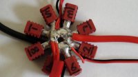
Hey Guys, this sort of sounds like its maybe the reason why I'm having an issue with PH. I have made a ring up using Deans plugs which form a continous ring, a very small one but still a ring.

Should I cut the + and - rings so they aren't continous?

@ Daivd, I would appreciate your input on this if possible. Do you think my Distribution ring could cause magnetic problems - EMI?

The issues I'm having with PH are very random and the X8 seems to hold better in certain headings.

Thanks,
Craig
View attachment 1651
 

Attachments

  • DSC00367-2.jpg
    DSC00367-2.jpg
    33.6 KB · Views: 267

Macsgrafs

Active Member
Hey Guys, this sort of sounds like its maybe the reason why I'm having an issue with PH. I have made a ring up using Deans plugs which form a continous ring, a very small one but still a ring.

Should I cut the + and - rings so they aren't continous?

@ Daivd, I would appreciate your input on this if possible. Do you think my Distribution ring could cause magnetic problems - EMI?

The issues I'm having with PH are very random and the X8 seems to hold better in certain headings.

Thanks,
Craig
View attachment 2777

Craig if its easy enough to break & resolder if needed, then go for it...I would be interested to know myself!

Ross
 

crcr

Member
Ross, I thought you would be fast asleep :)

I'm just not sure if I need to break both + and - and just one of them?

Craig
 

Craig, Ross, that is some distribution net and really as good as any that can be bought. However any problems that may manifest themselves from electric currents of very different magnitudes and times are very often due to the magnetic fields that concentrically surround the coductors (wires, copper planes, etc.) throughout their length. Your pictures shows 8 cables coming off of the net all going in different directions and routes to their relevant motors and other cables supplying UBECs, etc.. These routes are often taken close to other elctronic equipment (this also has currents travelling down conductors, of different magnitudes and times) and possibly 'conflicting' with each other and so causing intermittent blips on aircraft control hardware performance. In my view the problems more than likely arise from the magnetic fields of the power cables inducing spurious signals into other light current signal cables and or electronic equipment.
 

crcr

Member
Thanks David, so are you saying rather than breaking the loop I should try and get all the cables coming out of the distribution ring at the same place?

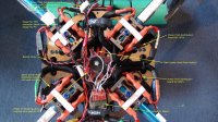
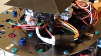
Here is a picture showing all the cables on the X8, the main power wires and now coming in from the same side, not as shown in the picture above.

View attachment 1655View attachment 1656
The white wires in the second photo have been replaced by the ones shown in the first photo but the setup is still exactly the same

Really appreciate your help,

Thanks,
Craig
 

Attachments

  • DSC00635-2.jpg
    DSC00635-2.jpg
    158.8 KB · Views: 292
  • DSC00297-2.jpg
    DSC00297-2.jpg
    150.8 KB · Views: 291
Last edited by a moderator:


Craig, what is important here is not where the cables emerge from the dis. ring but the route they take to their apprpriate destination...eg...motor. The closeness of the low signal cables to the distribution cables has potential for problems...eg...the white PPM wires are near to the black sleeved cables that presumably go the motors. Out of curiosity are all your connections soldered or do you have the motor cables bullet connected. The reason I ask is that I have experienced motor blips and a refusal to fire a motor up on more than one occasion...I eventually simply went to each of the motor bullet connectors on my quad and reseated all these connections and lo, the problem went away and has not returned. I am now going to replace all these bullit connectors with a stiffer 'spring' type that offer a better interference fit connection.
 

crcr

Member
Craig, what is important here is not where the cables emerge from the dis. ring but the route they take to their apprpriate destination...eg...motor. The closeness of the low signal cables to the distribution cables has potential for problems...eg...the white PPM wires are near to the black sleeved cables that presumably go the motors. Out of curiosity are all your connections soldered or do you have the motor cables bullet connected. The reason I ask is that I have experienced motor blips and a refusal to fire a motor up on more than one occasion...I eventually simply went to each of the motor bullet connectors on my quad and reseated all these connections and lo, the problem went away and has not returned. I am now going to replace all these bullit connectors with a stiffer 'spring' type that offer a better interference fit connection.

David, Yes the black sleeved cables are the motor cables, I'm just not sure how I can avoid having the signal wires close to the motor wires? Would it help if I had the PPM converter board on top of the top plate near the FC rather than underneath on top of the motor wires? The signal wires would still have to run past the motor wires and distribution board but at least they wouldn't be sitting directly on top?

Do you think this may help?

Yes all my motor cables to ESC are connected using 3.5mm bullet connectors, I will keep an eye on them and now that you've mentioned it, this will be the first thing to check if I have motor problems.

Thanks,
Craig
 
Last edited by a moderator:

Top