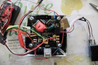
Mikrokopter MK power distribution board

Craig, I think you have got to do this with the move of PPM Converter to the top plate...it is relatively simple to do and try for effect soonest. Have you ever considered the screening of the cables...I was discussing this issue with a work colleague of mine who recalled a very similar problem on a helicopter some time ago and where they applied a fix of baco-foil screening around the cables...it fixed their problem. Of course the placement of the cables with this level of screening would have to be handled with extreme care so that the foil does not electrically short out other nearby components...Just a thought.
 

crcr

Member
Thanks David. I will move the PPM conveter board to the top plate and see what happens.

What is Baco-Foil, is that aluminium kitchen foil? I did try this around the battery cables but didn't make any difference. The shielding I have around the motor cables is "Flexo Conductive expandable braided sleeving" http://www.techflex.com/prod_CNN.asp but again I didn't notice any difference at all after adding this, so I have my fingers crossed that moving the PPM converter will do the trick, if not, I'm not sure what next??

Thanks,
Craig
 
Last edited by a moderator:

Craig, yes Baco-foil is kitchen foil. It does seem though that you have carried out any necessary screening already and with a top-drawer product. It just has to be then something like the move of the PPM board to fix it. I do though have to re-say my own experience with the blips where the reseating/replacement of the bullit connectors fixed the proble.
 

crcr

Member
I will check the bullet connectors also. Back to the distribution board/ring, do you think I need to make a cut to break the positive or negitive ring or do you think this is unlikely to be a problem?

Thanks heaps for your help, really appreciated.

Cheers,
Craig
 

Craig, if you have no other single conductors going through the centre of the ring then there is no requirement to 'cut' the ring. (If a single conductor went through the ring it is possible for 'other' currents to be induced that in turn possibly effect other circuits, equipment, etc.. It is just one of the many after-effects of electro-magnetic induction in such a small tightly packed space. Screening rids of it somewhat along with cable/conductor/circuit routing and placement of electrically sensitive equipment. This is the case for all electrical equipment regardless of size, type and manufacture...can you remember the occasions of loud noisey hums from Hi-FI setups of yesteryear...move a cable and the hum dissapears....same stuff going on here only a hell of a lot more expensive.
 

Craig, sorry to bore you with this, but if you do all the above and you still experience the problem and, you do not own an iffy FC, etc. it can only be dry/cracked solder joints...and MK carries a lot of soldering. I have experienced solder joints problems hundreds of times over the years on all sorts of equipment and they are extremely difficult to nail down.
 

Macsgrafs

Active Member
Ross, I thought you would be fast asleep :)

I'm just not sure if I need to break both + and - and just one of them?

Craig

im a night owl Craig ;) you know how it is some nights, you go to bed & cant sleep so you hit the forums for some night fun ;)
I have been following the conversation between yourself & David, very informative may I add. I dont have an option to move my I2C-PWM convertor as the ESC leads are to short..so I've wrapped it in heatshrink & will try covering it over with a screen to keep hopefully the magnetic effects screened from the FC & navi(when I get it).

Ross
 

crcr

Member
Thanks David, I have tried two different FC boards, one is brand new but as you meantion solder joints, the solder joints on the new boards all look like dry joints, I was wondering if the lead-free solder give that appearance?

Anyway, when I first changed to the new FC the first couple of flights were perfect and I thought the problem was solved but then it started doing it again. I have tried lots of different things and had lots of flights, I can get sometimes 4 or 5 perfect filghts and then the next flight it will take off again, so its very random :(

Thanks,
Craig
 

crcr

Member
im a night owl Craig ;) you know how it is some nights, you go to bed & cant sleep so you hit the forums for some night fun ;)
I have been following the conversation between yourself & David, very informative may I add. I dont have an option to move my I2C-PWM convertor as the ESC leads are to short..so I've wrapped it in heatshrink & will try covering it over with a screen to keep hopefully the magnetic effects screened from the FC & navi(when I get it).

Ross

I know what you mean, my wife hates these things as I hardly ever go to bed until the wee hours, its 1:40am here now :) its just one of those things that needs to be done ;)

I'm about to start moving my ESC signal wires now and will test in the morning. Will let you know how it goes.

Ross, to cut down the number of wires you have you could cut off the + and - wires from your ESC, you only need the signal if you are powering the converter board from the FC. Not sure if this would help the cause but I would think the less wires the better?

Cheers,
Craig
 

Craig, although I don't have any MK equipment, soldering is soldering. The board solder joints that you mention of, are they your joints or MKs ? Remember lead-free solder runs at a higher temperature and it is possible to hold the iron on for too long when soldering a connection resulting in possible damage to a component. I don't want this discussion to be despondant sounding and all downhill stuff but from what you have just entered it has to be something obscure to elude you thus far.
 

crcr

Member
David, the solder joints I'm talking about are MK's joints. I have seen on another forum somewhere that someone else was complaining about the MK quality control.

I don't use lead-free solder myself and all my joints are nice and shiny :)
 

Craig, it sounds as though your end-of-things is solid. I have also heard 'stories' about MK board quality but I don't know if they were soldering/connection or a component issue(s). I know it would be a big call but do you know anyone nearby that would be willing to swap boards for diagnostic purposes ?
 

Macsgrafs

Active Member
I'm going to bvuy some more blank circuit board & draw out a sheild to go between the FC board & the wire below, earth it out as such & see what happens ;) fingers crossed. I cant be bothered to take wires off of the ESC's...that's too much like hassle & I'm a very lazy person ;)

Ross
 

crcr

Member
Well guys, I moved the PPM converter above the centre plate away from the motor wires but it didn't make any difference at all :(

David I don't know anyone near me with a MK to swap the boards. I have a spare new board that I ordered a while back when i was having issues with the gyros but that board does the same thing.

What now?? :(

Thanks,
Craig
 

Craig, this is not a proposed answer to your problem(s) but is merely food for thought. This may all look and sound like very negative 'stuff' but in fact it is all very positive...you now know what is not causing it, so those items that you have covered so far can be eliminated from the argument. So what is left...judging by your earlier pics. all that remains is connectivity quality and the 'lower board' components. I don't have any experience of MK so it is difficult for me to comment on the actual components. I do though have many years experience of installing, servicing, fault diagnosis and finding of electronics and electro-mechanics...in that time it was established that, without any doubts whatsoever, the causes of these seemingly small and intermittent problems are to do with 1) connectivity caused by a poor interference fit, be it a single bullit connector or a flat ribbon mult-way connector...2) Components...very difficult to diagnose (unless you have available internal diagrams and diagnostic tools) meaning that the only diagnostic route is an expensive, and not always successful, replacement of parts...3) Operator (pilot) error...but unless you are doing something obviously avant-garde don't explore that path yet. I am sorry that we have not yet found the answer to your problem(s) but I will continue to think on it and get back to you if something brilliant comes of it.
 

crcr

Member
Thanks David, appreciate your help.

I wonder if it could be anything to do with the cables soldered to the underside of the FC board?
View attachment 1668

I have tried a thin aluminium plate (exact same size as MK boards) between the FC and Navi-Ctrl board with no luck. Do you think a bigger aluminium plate under the FC board would help anything? Not sure if having the distribution ring directly under the MK boards would cause any issues??

Because I moved the PPM converter board, the C+D lines from the FC to the converter are looped/coiled a bit because they are now too long, I can shorten these up, not sure if this would cause and magnetic interference or not??

Thanks,
Craig
 

Attachments

  • _MG_1475-- (2).jpg
    _MG_1475-- (2).jpg
    61.9 KB · Views: 240

Craig, it seems to me that you are carrying out all the right things. I don't think that installing a larger ali plate is the right thing to do at this time...it must be a time consuming job anyway. Coils of conductor carrying a current can always be a problem as the normal mag field that surrounds a conductor is condensed into a 'smaller' space and is effectively stronger...should be avoided if possible. Talking about possibilities can you somehow arrange your set up so that the dis ring is as far away as possible from the MK boards ? I do not know how you can do this but if you can and somehow feed all the other components you can eliminate this totally from the argument ? I guess it would be a lot of work though and quite difficult to achieve.
 

crcr

Member
I could put add another 15mm spacer under the FC board or maybe even 2 spacers and make it 30mm. Earlier I did increase the distance between the FC and Navi-Ctrl from 15mm to 25mm to try and get the compass further away from any power but didn't notice any difference.
Do you think raising a complete stack with spacers under the FC would do it or were you thinking to move them away from the distrbution ring by having it off the MK completely?

I will also shorten the C+D lines.

Thanks,
Craig
 

Craig, I guess what I'm suggesting is that the 'fault' may change in characteristics or dissapear completely. You seem to indicate that you can manifest the fault at will as it stands...see what happens if you make some dramatic changes...as long as it is safe to do so and there is no danger to your expensive aircraft. It is easy for others sitting in front of a screen suggesting things to do but to make it actually happen at the 'coal face' can be a different story.
 

Macsgrafs

Active Member
Craig, here's probably the easiest way to isolate things, still not 100% sure it will work, but for a few £'s it might be worth the effort. Buy some copper clad board as used for makign PCB's:- http://www.maplin.co.uk/copper-clad-boards-2112

Then make a square board big enough to cover over the power distribution ring like this as seen sideways on:-
View attachment 1669
Don't forget to earth/ attack all that copper to the neagative rail of your power dist boad or negative of the battery.

Ross
 

Attachments

  • screen1.jpg
    screen1.jpg
    37.9 KB · Views: 232

Top