Overlapping Propeller Designs

R_Lefebvre

Arducopter Developer
I'm starting this thread in the interested of not further hyjacking this thread:

http://www.multirotorforums.com/showthread.php?5825-Hamer-X4-Ultimate-Kopter-for-Filming-Industry

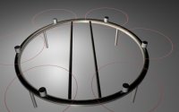
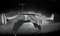
Some other photos of my multicopter build are here, if you're interested:

http://www.diydrones.com/forum/topics/new-octo-copter-design-build-thread?id=705844%3ATopic%3A970360&page=1#comments

I don't really fee like rehosting all the photos, and I'm sure the frame itself isn't of much interest here anyway.

But to go on with the discussion of overlapping props...

Rob
An interesting set of figures. I am wondering however what effect having more pitch on the lower blades has on Yaw stability.

Good question. I think as long as you don't have all the motors on the bottom going all one direciton, and the top motors in the opposite direction, I think the FC will be able to balance it. But, it would have to be tested.

Thanks for the info RLefebvre..very valuable. I'm looking to keep the octo's diameter the same as my hexa with 13" props which is approx 760mm. Would it be possible to figure out the required amount of overlap for the octo with these numbers?

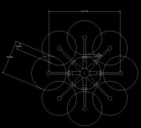
I've already done the math on that as it was my original design. A 756mm octo with 13" props would have an 18% overlap.
 

R_Lefebvre

Arducopter Developer
One question I have, it how much vertical disk seperation is enough? I used 30mm in my test because that's what I had. Could we use less? I haven't seen any disk deflection, ever, on these things, but I can't say it doesn't happen in flight.

Something else that might blow your mind: There is also theory that having the mass hanging below the center of lift is less stable than if you put the mass on top. Look at how NASA designed the drop ship of the Mars Rover. ;)
 

DucktileMedia

Drone Enthusiast
I've had this idea of a ring that I never finished building as it weighed more. But the idea of staggering an X8 was of interest. here is the cad drawing I made a while back in hex form but I also imagined it in a staggered 8 config based off of a ring concept.

View attachment 6267

There was also this idea which never took off for some reason??

View attachment 6268
 

Attachments

  • ring concept.jpg
    ring concept.jpg
    100.7 KB · Views: 761
  • spreading legs.jpg
    spreading legs.jpg
    90.3 KB · Views: 798

kloner

Aerial DP
are you asking about coaxial type setups? unfamilliar with the term overlapping

Thank god that was spreading feet and not spreading something else
 

R_Lefebvre

Arducopter Developer
Haha, for a second I thought the second picture was NSFW. ;)

The ring idea is interesting. Probably much stiffer than using booms. Going with overlapping blades would shrink the ring down to a much more reasonable size. In fact, you could cut the whole thing out of CF I think. For sure, you could make it out of aluminum plate.

I've had this idea of a ring that I never finished building as it weighed more. But the idea of staggering an X8 was of interest. here is the cad drawing I made a while back in hex form but I also imagined it in a staggered 8 config based off of a ring concept.

View attachment 8243

There was also this idea which never took off for some reason??

View attachment 8244
 

R_Lefebvre

Arducopter Developer
are you asking about coaxial type setups? unfamilliar with the term overlapping

kloner, not overlapping just partially, not a full coaxial. There is theory that says that you can overlap up to 40% of the disk area without losing efficiency (which you do with a Coaxial), and I proved it out in testing. I allows you to shrink an octo to a more manageable size.

Here's a picture of my layout.

View attachment 6269
 

Attachments

  • Rob Octo 3.jpg
    Rob Octo 3.jpg
    87.7 KB · Views: 656


R_Lefebvre

Arducopter Developer
The only real downside I see is that... I understand that some stability is gained with longer arms. Is this true?
 

jes1111

Active Member
Sorry - still need to know (from the earlier thread and the DIYD write-up) - what is "D/L"?

Re: the "efficiency loss" with a coax setup - you really need to test with higher-pitch props on the bottom. Of course, then you have test to different combinations of pitch, different profiles, different spacings, etc. - big subject! Also, I get kinda annoyed at the casual dismissal of coax as "less efficient" (not that you're doing that, Rob). Less efficient at what? It's a machine, built to do a job within a set of wider parameters (cost, safety, size, weight, duration, etc.) - coax doesn't diminish the craft's potential to discharge its specific role efficiently (unless, perhaps, your sole criteria is flight time, to the exclusion of all other considerations). In assessing coax vs. any other layout, there may be an "efficiency loss" resulting in marginally shorter flight time for the same battery payload. But I do believe that flight duration is the least important consideration for heavy-weight aerial filming as long as there is enough juice available to get in position, get the shot and get back to the ground. Btw - a coax setup will, by definition, be lighter than the equivalent hexa or octo machine - so that needs to be accounted for in the calculations, too.

Longer arms do not produce more stability, per se - they increase the moments of inertia and therefore slow the response of the airframe to inputs - that can be perceived as greater stability - but it would also be FC- and tuning-specific.

This overlapping idea is interesting - I haven't seen it explored/measured elsewhere. Rock on - I'm listening! :)
 
Last edited by a moderator:

R_Lefebvre

Arducopter Developer
D/L is prop diameter over motor spacing. So for example, my D/L = 1.18 would mean a prop of 330mm and a motor spacing of 280mm. The theory says that somewhere around D/L of 1.2 to 1.3, you may actually achieve thrust efficiency greater than a single motor alone (by about 5%). But this is practically impossible to prove out conclusively in our simple labs.

The whole overlapping blade idea was proposed to me by Brad Hughey. A very smart guy, and one of the original people to attempt a manned electric helicopter. He is not suggesting that it be done in the search of this elusive 5% efficiency gain, but simply when the goal is to achieve the largest amount of blade area in the least amount of space on a multirotor airframe. That's pretty important when you're trying to lift a man using a multirotor platform. It's also important to me when I'm trying to build a non-folding Octo that is easy to transport.

I totally understand what you are saying about "efficiency". Obviously the term applies to thrust/watt in this case. But, that doesn't need to be the primary goal of every MR design. And yes, the weight reduction inherent in an X8 design should not be discounted.

Glad to hear I'm not necessarily shooting myself in the foot in terms of stability on a small octo design.
 
Last edited by a moderator:

DucktileMedia

Drone Enthusiast
I was thinking about the ring because i am a metal fabricator and that is super cheap and easy to manufacture. I also thought it might transmit vibrations differently than arms to my advantage. The big problem is that you still need a core to balance batteries, electronics and the gimbal which all kinda like to be in the center. My proto aluminum tube had cables with rubber rings that reached to the center to hold the gimbal which would help isolate vibes even more. It might have worked but in the end it didnt solve the problems of being smaller and more portable than the arm design. But certainly overlapping motors would help shrink this down substantially. the other problem with helis is that you want it small to travel with but as big as possible in the air for flying LOS. My perfect heli would be something like an overlapping X8 ring that had 2 really long arms that telescope out for visual orientation so you dont get spooked by your camera guy spinning the turret 399' in the air.
 

kloner

Aerial DP
rob, out of curiosity, does having the motors on the same plane, not one top, one bottom make a difference with overlapping like this? hybrid coax like

does it take away the ability to get those d/l calculations to your liking?

i've ran the kloners frame and a discovery frame. Two are almost identicle, but the motor spacing is alot different. one flies 5 minutes, the other flies 12 minutes all at the same speed, same motors, controller, everything. am absolutely stumped why, but am going into further r&d to find out. theres something about tickling calculated spacing/angles versus real life prop spacing at play, just gotta find it. I realize your goal being different, but point being don't be afraid to try something even further from outside the box and see if it changes things in your favor. There is alot going on in multirotor engineering, like rocket science

you got my attention, can't wait to see where you wind up with this
 

R_Lefebvre

Arducopter Developer
I'm not quite following what you are saying. You want to overlap, but have all the motors exactly in the same plane? That would require you to have a drivetrain between all the rotors, to keep the phasing right so the blades don't collide. That then would require variable pitch so that you have control. And now you've build yourself a Chinook. ;)

Or did you mean, instead of mounting some up, some down, keep them on the same plane, but space them just a small mount? Have a close look at my photo, and you'll see I did that, just using 30mm spacers. In fact I tested both ways, spacers, and with one up and one down. I could see little difference, and this agreed with the theory which also says in the range we are talking, the disk separation distance doesn't matter much.
 

kloner

Aerial DP
i see you got a motor higher then lower on the same plane. i was asking if you made one motor up, one down, but overlapped if it did the same thing
 

jes1111

Active Member
ah - now I understand ;)

You mentioned vertical CG placement in your DIYD write-up - that's an area of great interest to me. Hanging the camera under the centre of the disc is clearly a practical necessity rather than an optimum solution. The ideal is to have the CG coincident with the centre of thrust, although a small variation (+/-5cm vertically) doesn't produce any noticeable difference. Mathematically (from a published academic paper) having the CG above the centre of thrust (by up to about 10cm IIRC) yields a better inherent stability (i.e. it would be easier if you were trying to fly it entirely manually) - but any competent FC shouldn't need that assistance.

What does change is the moments of inertia, in the same way as longer arms. So hanging a big, heavy gimbal with a big, heavy camera under the frame will slow the craft's roll/pitch responses. The craft will always rotate around its centre of gravity - the further that point is displaced from the centre of thrust (in any direction), the more work the motors have to do to effect a change of attitude. This can be visualised as holding a broom-stick with a weight on the end - the closer your hand is to the weight, the easier is to rotate the stick in space.

One thing that a heavy, under-slung load does not achieve is greater inherent stability. This common misconception assumes the camera/gimbal acts like the weight of a pendulum, forcing the craft back to an upright position. It doesn't, because the definition of a pendulum is that it has a fixed pivot point - not the case for a flying machine ;). Simple test - hold a bottom-heavy quad at a 45º angle to the ground and drop it - it will not rotate as it falls: it will hit the ground still at a 45º angle!
 
Last edited by a moderator:


R_Lefebvre

Arducopter Developer
i see you got a motor higher then lower on the same plane. i was asking if you made one motor up, one down, but overlapped if it did the same thing

Ah, OK. I tested that too, and it doesn't seem to make a lot of difference. In fact, I think that is the data I presented in the graph. I did the 30mm spacer test after my good servo tester broke, so again, I didn't present that data.

jes, I should link you to a few other really interesting posts on DIYDrones if you want to read them. There's one about this overlapping disk stuff, and another about the CG.

I have had the idea that I could put the batteries on top of the frame, instead of underneath. This will bring the CG closer to the plane of the motors. The disadvantage here is that it will also bring the batteries closer to the magnetometer, which is bad. I think the ideal is probably to put the batteries up top, but move the mag down to the bottom of the landing legs. The GPS needs to stay up top. Luckily this is possible with our system.
 

R_Lefebvre

Arducopter Developer
I really like the ring idea. You might be on to something regarding vibrations.

Check this out http://techcrunch.com/2011/04/13/roundtail-bike-cool-or-just-loopy/

Same shape, totally different concept, however.

I don't doubt the 10 times the flex thing however. It's easy to achieve, because the triangular bike frame probably approaches ZERO flex! So it's not hard to be 10 times more than zero. ;)

Still, if the goal is just some flex, the same could be achieved much easier than the hoopy thing.
 

matwelli

Member
There is also theory that having the mass hanging below the center of lift is less stable than if you put the mass on top. Look at how NASA designed the drop ship of the Mars Rover. ;)

Yep, i would agree with that, in fact if making a bicopter its the only way to achieve decent control, like balancing a broomstick vertically on your finger
 

matwelli

Member
kloner, not overlapping just partially, not a full coaxial. There is theory that says that you can overlap up to 40% of the disk area without losing efficiency (which you do with a Coaxial), and I proved it out in testing. I allows you to shrink an octo to a more manageable size.

Here's a picture of my layout.

View attachment 8245

im encouraged to hear this, was just thinking last nite on how to build a Y6 with all the motors on top, and if overlapping prop disc's works, thats just fantastic
 

Top