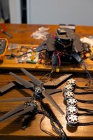
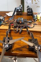
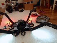
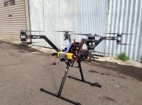
So, the Vulcan frame.
Very simple, no frills, but well thought out. There are pre-drilled holes in the carbon plates for almost every fixing configuration imaginable.
I have some small gripes:
- my package arrived with some key pieces missing...bolt kits, stand-off, arm patch plates. It's pretty simple to get some of these things wrong when packaging kits, so no real harm done. They came about 2 weeks later. But I am still a few stand-off down, because I didn't inventory every single thing.
- some of the parts aren't perfect, hole alignments between carbon fibre plates and aluminium components aren't perfect, and so a bit of drilling is required. Also one of my aluminium arms had a corner sheared off. Only a small visual defect.
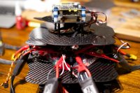
- the motor arm plates have 6 radial slots, so you can rotate the motors to find the best way to fix them. There was only one orientation that let me mount the KDE 4012's (which also have holes drilled all over the place) AND get a stand-off fixed to the end of the plate. Even then, it's a super tight fit to fix the stand-offs joining the two motor plates, like metal on metal tight fit. The KDE mounting adaptors were too big for the arm plates to use. Rather than 4 stand-offs on each pair of arm plates, I found a way to use 3 which fit better. Although I could have re-drilled everything, I guess!
- the hole pattern on the top plate almost, but not quite entirely fit the hole pattern of the Hoverfly Pro boards, so re-drilling them all out is necessary. So close, yet so far....!
The last two points aren't really Vulcan's fault, but it would be good to see some kind of standardisation on fixing spacings amongst the component manufacturers. One of the advantages of the Vulcan frame is the adaptability - but that only goes so far if I need to re-drill holes for everything.
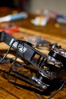
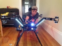
Mantis arms:
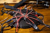
The X8 configuration is a tight fit in this frame. The mantis arms are quite slim, and fitting the motor wires down them is a challenge. I used a paperclip on the end of a string to pull the 6 motor cables through. A bit of force is needed to overcome the friction of the silicone wire sheath on the aluminium.
All the arm fixings - motor mounts, arm plates, and fixing to the top and bottom plates go through the arms. So you've got to dodge the wires inside. It would be impossible to fix the arms first and then pull the wires through, so this bit is a tedious and time consuming task. It is probably much easier if you only used 1 motor per arm.
There was a construction order that worked best for me.
1. Fix the motors to the arm plates.
2. Fix the stand-offs to the top motor arm plate only. This is so you can remember which motor is which for connecting to the ESC's.
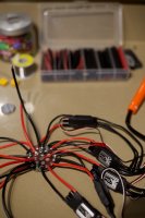
3. Feed the motor cables through the arms. Remember to colour code the top and bottom motor wire ends (I used different colour heat shrink on the bullet connectors), or you'll mix them up when plugging into the ESC's.
4. Fix the motor arm plates through the arm. This is the first juggling act, especially if you have heavy motors. You're probing cables out of the way, feeding bolts through, trying not to drop washers off...you get the idea.
5. Finish fixing the arms plates together with the stand-offs.
6. Bolt the arm patch plates through. You'll need to probe to push wires out of the way. This can take some time.
7. Connect wires to the ESC and test the direction of spin before fixing the arms onto the top & bottom plates.
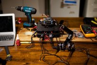
This is the last part I got to, because I cannot get my Hoverfly Pro to connect to the setup software. So I'll post some more when I can go further!
On a side note, this is a really noisy beast, even when not flying. The KDE ESC's and the Hoverfly Pro all beep constantly when on the ground but not armed. Don't test this machine late at night in a house full of light sleepers.

")