One can determine the current loads either mathematically or though various on board devices and sensors. For those building units for serious cinema work they have the option of setting up a bench test where calibrated equipment can be used to build a data sheet. Experimenters can, and do, set up thrust stands to measure electrical loads from various prop/motor/ESC/battery combinations and used the test derived data to extrapolate a total load. If one is building a large heavy lifter and doesn't trust manufacturer advertising spec sheets designed as a sales tool that a smart way to go. Costs more because one buys more product as single test samples but they end up with very accurate reference data by bench running a system with a battery providing constantly declining voltage instead of a constant voltage. Tip: Some of the manufacturer motor/prop data sheets are fictional in their representations.
Some FC's provide data referencing electrical information that is broadcast via radio telemetry or an OSD that permits the user to obtain relevant data. The mathematical method provides information that is more of an estimate. It will be close but does not provide for spikes due to defective equipment. Those that use E-CALC should not expect 100% accuracy with the results obtained from their input data. E-CALC can be off by a considerable margin, but it's a good start.
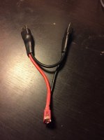
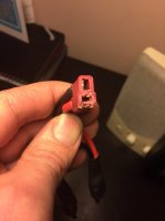
There was a time Deans connectors were the hot ticket, but there wasn't much else obtainable for the average modeler that was as affordable. The use of Deans was initiated by the RC car and early RC aero electric flyers. The big loads were generated by RC cars while the RC aero guys typically used a lot smaller batteries. The use of really high current systems didn't start until only about 8 years or so ago with the electric aero crowd and they were not many in number since most of them were Europeans that came over to fly high visibility 3d and precision contests. They eventually moved away from Deans connectors after they experienced heat issues and found them quite difficult to disconnect in the tight confines of an airplane fuselage. Bottom line is there are quite a few connector designs that work great as long as they are sized appropriately for the intended purpose. The XT connector is obtainable in amp ratings of 60 and 90 that I know of. EC connectors have several different sizes, 3 and 5 being a couple of off the top examples. Anderson Power Poles start out about 15 amps and sizing goes up to hundreds of amps. There are others if one chooses to do the research. A nice thing about connectors that are soldered up without a plastic housing around them is the plastic cannot be melted or compromised from the application of excessive heat during the soldering process.
Bottom line, regardless of what one uses they should first perform the research necessary to generate a rough estimate of a systems electrical load. That's probably the hardest part of building a custom copter because you have to first determine the intended purpose, establishing a rough size and weight estimate, then research and list out components/capabilities to get their weights to estimate the aircraft's total weight and component requirements. Then revise the component selection if they come up a little short based upon actual weight. A responsible engineer never designs to a minimum standard but instead allows some "head room" for transients that are likely some point to exceed the minimum design standard. Wiring and connectors are great places to provide head room because they are natural choke points. A 10% to 25% fudge factor can eliminate a lot of grief. I like to use a term I call the "law of minimums". Designing to the law of minimums means the smallest and least important component will cause the demise of the aircraft should it fail. One can use Deans connectors for a primary power connection and not experience any problems if that's the connector type they prefer, as long as they sized the connector accordingly.


