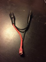
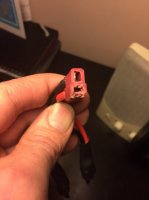
Melting deans plug - crashed!

Flydigital

Member
I have 2 3s lipos in series to create 6s power for an octocopter. Whilst flying I lost all power and found that my positive connection on the deans had got so hot it sunk into the plastic body and disconnected. I had a look at the connection and the gold contact was completely buried. Photo show it almost appearing on outer side.
Is this a substandard deans or is my current too high? is the 2 x 3s in series a potential problem too?

Octocopter
8 x Turnigy Multistar 45 Amp Multi-rotor Brushless ESC 2-6S (OPTO)
8 x 4112-320KV Turnigy Multistar 22 Pole Brushless Multi-Rotor
6s 5000mAh Lipo
 

Attachments

  • deans2.jpg
    deans2.jpg
    46.4 KB · Views: 341
  • IMG_3978.JPG
    IMG_3978.JPG
    26.3 KB · Views: 383

Carapau

Tek care, lambs ont road, MRF Moderator
Well Deans plugs are only rated to about 70amps I believe although quite hard to find specifics. So I suspect the melting has been purely caused by over amping.
 

PeteDee

Mr take no prisoners!
And any time you solder a lead and add just a little too much heat that rating will reduce, I would probably be using some bigger connectors like XT90 or 6mm plugs on something that size.
 

Old Man

Active Member
Where your supplier obtained the connectors plays a part as well. Unless obtained from a supplier that provides hard specification data you can't know an amp rating. There are so many offshore manufacturers one cannot be assured of a quality level, and some makers seriously cut corners with components to increase profitability.


Sent from my iPhone using Tapatalk


Carapau

Tek care, lambs ont road, MRF Moderator
Wise choice


Sent from my iPhone using Tapatalk
 
Last edited by a moderator:

maxwelltub

Member
EC5's are a great choice. Once you get the hang of it they are way easy to solder. Use a butane hobby torch and you can bang them out really quick and very secure. Never had an issue, sometime the bullet connections can become lose in the plastic casing if not seated properly, however even in that situation it would be unlikely it would disconnect the electrical connection..
 

Pumpkinguy

Member
I've used castle creations exclusively on my new build. 6.5mm for battery wires. They also do a 4, 5.5 and 8mm. Just another option that doesn't get mentioned much and look to be high quality. Rated for crazy loads depending on the size you choose.
 

Carapau

Tek care, lambs ont road, MRF Moderator
If you want to go down the bullet route the problem is that often they are just bare bullets which need to have heat shrink added to them to cover the terminals. This is effective but it can still leave a risk of shorting when in transit due to the nature of manual heat shrinking. I recently found SupraX bullets which come with an excellent plastic housing. The 6mm ones are rated to 200A constant! The ones with the screw on backs are very easy to fit and for high loads I have yet to find anything else that comes close.
 

Flydigital

Member
I'm going to go with bullets and yes I can see how you would need to get the heat shrink just right to avoid shorts.
Question about Amps? Can I measure this through a formula or do I need to actually measure in circuit? If I measure myself I thought without props on the Amps may be different as the motors won't be working as hard. After my crash I think I need to know the numbers!
 

Carapau

Tek care, lambs ont road, MRF Moderator
You can get some telemetry sensors that will tell you the amps otherwise its quite hard. You could calculate the average amp draw for a flight. Take off an hover for a few minutes and then land. Note the time that the flight landed and then see how many mAh it takes to recharge the batteries. So, if you used 5000mAh in 4minutes then 5000/4=mAh per minute ie 1250mAh/m and then times this by 60 to get the actual currant so in this case 7500mA or 75A. Well, I think that's the right maths to use. All US folk please note the correct term used here ie MATHS with an S hehehe


I think you need to know a hell of a lot more about your hobby do some reading and get informed before you dive in at the deep end.
I would not trust deans above 50 amps they are a crap connector, I do not know why anyone would use them today with so many superior choices available

Roughly @ 14 volts 0.3 mtrs long with 3% loss:-
17awg = 35 amps
16awg = 40/45 amps
15awg = 50 amps
14awg = 60/70 amps
13awg = 80/90 amps
12awg = 100 amps
10awg = 150 amps
9awg = 200 amps
8awg = 290 amps
Regards - bruce
 

Old Man

Active Member
I'm going to go with bullets and yes I can see how you would need to get the heat shrink just right to avoid shorts.
Question about Amps? Can I measure this through a formula or do I need to actually measure in circuit? If I measure myself I thought without props on the Amps may be different as the motors won't be working as hard. After my crash I think I need to know the numbers!

Once a system is set up and dialed in there's not much call for separating bullet connectors. It makes far more sense to use a single piece of heat shrink to cover the entire connector assembly from one end to the other. There's also the added benefit of assuring the connectors stay together.
 

Flydigital

Member
I think you need to know a hell of a lot more about your hobby do some reading and get informed before you dive in at the deep end.
I would not trust deans above 50 amps they are a crap connector, I do not know why anyone would use them today with so many superior choices available

Yes. More to learn it seems but so far I've been learning through mistakes and problems. And reading a few forums on this issue.
This is old thread admittedly:
http://www.rcgroups.com/forums/showthread.php?t=1281209

But it seems to contradict your view. Eg: 'deans are the best. I saw it draw 100amps'

I would be wary of this given my experience of a melt down. I'll upgrade to be safe if there is genuinely a better option. XT60 gets a good review but it's only 3.5mm.

And how does someone see a plane / multirotor 'pull 100amps'? Is this through calculation (see above) or by onboarding an inline power meter (see above)?

Lots to learn indeed. o_O
 

Old Man

Active Member
One can determine the current loads either mathematically or though various on board devices and sensors. For those building units for serious cinema work they have the option of setting up a bench test where calibrated equipment can be used to build a data sheet. Experimenters can, and do, set up thrust stands to measure electrical loads from various prop/motor/ESC/battery combinations and used the test derived data to extrapolate a total load. If one is building a large heavy lifter and doesn't trust manufacturer advertising spec sheets designed as a sales tool that a smart way to go. Costs more because one buys more product as single test samples but they end up with very accurate reference data by bench running a system with a battery providing constantly declining voltage instead of a constant voltage. Tip: Some of the manufacturer motor/prop data sheets are fictional in their representations.

Some FC's provide data referencing electrical information that is broadcast via radio telemetry or an OSD that permits the user to obtain relevant data. The mathematical method provides information that is more of an estimate. It will be close but does not provide for spikes due to defective equipment. Those that use E-CALC should not expect 100% accuracy with the results obtained from their input data. E-CALC can be off by a considerable margin, but it's a good start.

There was a time Deans connectors were the hot ticket, but there wasn't much else obtainable for the average modeler that was as affordable. The use of Deans was initiated by the RC car and early RC aero electric flyers. The big loads were generated by RC cars while the RC aero guys typically used a lot smaller batteries. The use of really high current systems didn't start until only about 8 years or so ago with the electric aero crowd and they were not many in number since most of them were Europeans that came over to fly high visibility 3d and precision contests. They eventually moved away from Deans connectors after they experienced heat issues and found them quite difficult to disconnect in the tight confines of an airplane fuselage. Bottom line is there are quite a few connector designs that work great as long as they are sized appropriately for the intended purpose. The XT connector is obtainable in amp ratings of 60 and 90 that I know of. EC connectors have several different sizes, 3 and 5 being a couple of off the top examples. Anderson Power Poles start out about 15 amps and sizing goes up to hundreds of amps. There are others if one chooses to do the research. A nice thing about connectors that are soldered up without a plastic housing around them is the plastic cannot be melted or compromised from the application of excessive heat during the soldering process.

Bottom line, regardless of what one uses they should first perform the research necessary to generate a rough estimate of a systems electrical load. That's probably the hardest part of building a custom copter because you have to first determine the intended purpose, establishing a rough size and weight estimate, then research and list out components/capabilities to get their weights to estimate the aircraft's total weight and component requirements. Then revise the component selection if they come up a little short based upon actual weight. A responsible engineer never designs to a minimum standard but instead allows some "head room" for transients that are likely some point to exceed the minimum design standard. Wiring and connectors are great places to provide head room because they are natural choke points. A 10% to 25% fudge factor can eliminate a lot of grief. I like to use a term I call the "law of minimums". Designing to the law of minimums means the smallest and least important component will cause the demise of the aircraft should it fail. One can use Deans connectors for a primary power connection and not experience any problems if that's the connector type they prefer, as long as they sized the connector accordingly.
 

eskil23

Wikipedia Photographer
Internal resistance in the conductor is what's causing the heat. The material and cross section of the conductor is what determines the resistance (and length off cource, but that is not really relevant here). Bruce 365 posted a list of current ratings for different wires (although I'm more used to mm² than AWG).

Connectors should have the same cross section as the wires they connect. But in connectors there are more factors that can increase resistance and cause overheating (after all, it was the connector that was overheating, not the wire). Dirt and oxide on the connectors is the most common one.
 
Last edited by a moderator:

Flydigital

Member
I realised the flight controller - Pixhawk - keeps logs of the flights. When I was at maximum throttle it went up to 6000 - Assume that's 60amps. These were surges only when rapidly climbing and longest was for about 5 seconds or so to shoot up to 88m. So anyway I'm assuming this is what fried my deans (or fake deans I imagine). My plan now is to use EC3s across all my batteries. They are rated to 60 amps.
In my 2 MCs, the smaller is F550 which will be way below this so EC3s will be fine. For the Octocopter where I had the crash I use 2 3sLipos in series. So my Y connector I think should be EC5 connection where it connects with the actual MC. I this sound thinking? If I don't need the EC5s everywhere I figured keeping it sleeker at EC3 would be better. EC5 comes into play where the 6s (2 x 3s) configuration comes into play. Then wire it into the power hub with 12AG wire.
Thanks for any input here!
 

glider

Member
Correct if wrong, but the length of the battery wire is also a factor and the weakest link in the wire will be the hottest point.
 

Top