Hoverfly First time multi-rotor builder - need some help

eddarack

Member
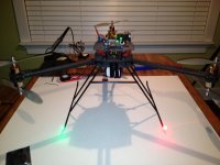
I'm a multi-rotor neophyte who is building my first craft. I've designed and built a frame (a Y6, based on the Hoverfly Pro and Hoverfly GPS), procured all requisite components, and I'm now completing the project. Please pardon my ignorance - and thank you in advance to anyone who responds to this - but I have some basic questions. The first concerns how to wire my ESCs to my motors. I'm using Turnigy Plush 25 amp ESCs and Balsa Products A2212-13 Brushless Outrunner motors. My first question is: The ESCs have outgoing leads labeled A, B, and C; The motors have three incoming leads: Red, Yellow, and Black. I need to configure for clockwise, and CCW - What connects to what?
Here is the URL for the the motors:
http://www.gravesrc.com/BALSA_PRODUCTS_A2212_13_Brushless_Outrunner_Motor_p/bpa2212-13.htm

And here is the URL for the ESCs:
http://www.hobbyking.com/hobbyking/store/uh_viewItem.asp?idProduct=2163

Thank you very much in advance for your responses; I'll undoubtedly have more to come.

Best,
Ed
 

Bowley

Member
Ed, just connect the wires up any way and if they spin the right way then alls good, if not just swap 2 of the wires round.
 

Webheadfred

Air Traffic Controller
I agree with Bowley. As you're building and testing, make a chart with A B C and under it Red Yellow Black. Wire up the ESC-motor-receiver-battery combo for an off-multi test, and note the direction it rotates. You'll eventually need two of this direction anyway. If it's CW, cool. If it's CCW, cool. Note either CCW or CW next to your chart. To make it spin in the opposite direction, simply make another chart with A B C and then Yellow Red Black and write the opposite of what you discovered (CW or CCW) next to it. All the motors and ESC are wired the same. Build your multi with this chart in mind and as you build, you'll know which arm to wire which way. Of course if you're using bullet connectors, it's really no issue as you can just swap any two wires to get the motor to rotate in the other direction. Always check the multi WITHOUT props on after it connect to the HFP to be sure everything is rotating in the required direction. Actually, the props should be the very last thing you put on before you're ready for your very first flight. Be sure the props are attached to the correct motor as well. The props should turn to push air down. Take your time. Have fun.
 

eddarack

Member
Thank you all very much!
I thought that maybe there would have been a common connection (black always connects to A, and then swap B and C relative to yellow and red for CW and CCW), but apparently not. These ESCs are also BECs, so I'll just do as suggested and first just plug into throttle port on my receiver and see which direction it spins. I'll definitely not be putting on the props until the end.
Again, thank you very much.
 

eddarack

Member
OK, so my next question:
I'm programming the ESCs right now (Turnigy Plush 25 Amp, with BEC). I have a Turnigy Programming card. As per the Hoverfly instructions, I've set:
Brake: Off
Battery Type: Ni-xx
Cut Off Type:Soft cut
Timing Mode: Medium
Start Mode: The Hoverfly manual states to use "Hard or Fast (NEVER soft), but the options on the card are: Normal, soft, very soft. So without the Hard or Fast option, I'm just going to use Normal
Governor Mode: Off
There is no throttle smoothing option available on this ESC card

There is cut off voltage adjustment on the card; the choices are: low, middle, high. The manual's ESC configuration values chart, however, does not mention this parameter. Do I set the Cut off voltage as low, medium, or high?
Thanks in advance for help with this.
Best,
Ed
 
Last edited by a moderator:

Webheadfred

Air Traffic Controller
I think I set mine to low. I want as much power for as long as I can get it. When you're ready to fly, weigh it and go to ecalc and get an estimate of your flight time. Set a timer on your radio or have some sort of timer and as you approach that time limit, hover low to the ground. As your battery starts to lose it's power you'll find that you need more and more throttle to stay up, and of course eventually, you won't be able to. You then make the decision on how much time you can fly and get back to land safely. This is your flight time. Leave enough room for error. There is some discussion somewhere about the longevity of the LiPo battery and draining it this much but that's another issue. You're trying to find out your flight time. Be aware that a lot of maneuvering and such will take more power than just hovering so that too can affect your time. I did this with mine and I leave 2 minutes to bring her down and land. Sometimes I can hover a good bit more and sometimes not. Eventually, you can put voltage monitors onboard that either beep and/or downlink voltage info, but in any case, with your unique multi, you have to find these limits for each setup. My small quad, I can literally zip around and fly figure eights for 16 minutes. My Hex, I get a solid 8 minutes and have to land carrying the camera and such. Have fun.
 
Last edited by a moderator:


eddarack

Member
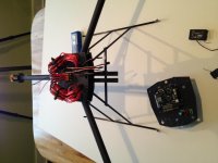
OK, so I completed the power distribution block and have wired all the ESCs to the requisite motors. As per the Hoverfly manual for the Y6 configuration, all top motors spin clockwise, and the bottom motors spin counter clockwise - when viewed from top down on the craft with all motors mounted. The motors are of course all spinning in the same direction, but because they are 180 degrees axially offset from one another on the end of each arm, the effective rotation of the bottom motors are CCW - so top prop (when mounted) spins CW and bottom prop spins CCW. I'm sure I'm making this way more complicated than I should, but I want to make absolutely sure I have this right.
View attachment 11473
 

Attachments

  • photo.jpg
    photo.jpg
    131.4 KB · Views: 230


Webheadfred

Air Traffic Controller
That is absolutely correct. The nice thing about the coaxial setup is that all the motors are wired identically. Be sure when its time to mount the props, (you still need 3 regular and 3 pusher props) that you must mount them with the numbers facing up. The Pushers should go on the top and the regular should go on the bottom. Be sure to check this as I'm doing it from memory.
 
Last edited by a moderator:

eddarack

Member
Thank you very much!
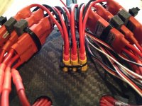
It's a distribution block I figured out by tinkering with HobbyKing XT60 connectors. It is a configuration of six of them, two sets of three side-by-side (epoxied) and then the two sets epoxied positive end to positive end for the final block of 12 total terminals. I shaved the raised "+" off to make them go together flush. The front block of three XT60s is positive, and the rear is neg. I soldered individual bullet connectors with shrink tape pushed about 1/64 above the base of each bullet connector, so no metal showing when plugged in. I could have done this better, though. You'll notice I use screws to mechanically squeeze the block into the carbon fiber base plate. I engineered all the parts to the UAV and they were milled in a 3-Axis mill (1/10,000 inch precision). If I had actually built the block first, then measured it with a caliper micrometer, It would have slipped in much cleaner. The way I did it, however, was to engineer in some added space. Luckily, the way the XT60s are designed allowed me to screw in some (4) 4-40 cap screws, to which I applied some permatex threadlocker blue. Not sure how effective this will be, but the block is in there very firmly. Unfortunately, the epoxy broke when I was pushing in the power leads from the ESCs, so I zipped tied a collar, and now it is very solid. I'll probably CA the zip tie. I don't really like the idea of using any glue. I'm trying to make all of this mechanically secured.
I should note that I was at first going to use the XT-60s for both ends, but space and weight are at a premium with this, so it dawned on me that it would be just fine to use bullet connectors to the block of XT-60s.
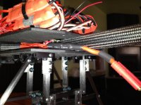
On the bottom side, I used 16 gauge HobbyKing fine strand wire (kind of like Ultrawire), individual lines soldered into each terminal, at about a 30 degree angle (outward - opposed - negatives angled to one side, and positives angled to another). This was so that nothing would be squeezed when I mounted the two plates together which hold the arms in place. I had just 3/4 inch. I soldered the 6 negatives to a ten guage piece of HobbyKing fine strand wire, and the same with the 6 positives, and then to their proprietary plug. I designed the UAV so that the battery cage can take one or two 5.0 or 6.0 Amp HobbyKing batteries. I'll have to wire up a parallel splitter to hold two. I kind of doubt that this will be able to lift the extra weight though...
View attachment 11474View attachment 11475
 

Attachments

  • photo.jpg
    photo.jpg
    143.9 KB · Views: 224
  • IMG_6390.jpg
    IMG_6390.jpg
    137.6 KB · Views: 256

eddarack

Member
OK, great Fred. Thank you very much (again). Very much appreciate it.
And that was going to be my next question - mounting propellers. I have 8 props total, APC composite propellers, 4 10 by 4.7 slo flyers and 4 10 by 4.7 slo flyer pushers (so a spare for each). And I'm confused about how to mount them. So when you say mount them with the numbers facing up, up for both (when looking down on the craft with props mounted), or up relative to the shaft of each, so when looking down on the craft with props mounted, numbers up on the top motors but then down on the bottom motors?
Also, the props have a distinct leading edge to them. Does the way the propeller is oriented and will spin matter relative to the leading / trailing edge? Or does this not matter.
Thanks again,
Ed


Webheadfred

Air Traffic Controller
yeah.... you figured it out.... the lettering faces top as you're looking down on the Y6. As the motors spin, picture the prop spinning with it and you want the air on all of them pushing down. Keep up the good work!
 

eddarack

Member
Thanks, Fred. It was your advice (pusher on top, numbers up) that got me headed in the right direction and got it to all go together.
Best,
Ed
 

eddarack

Member
OK, so now for a few more questions.
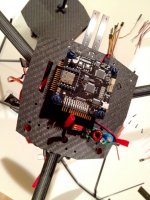
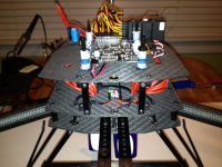
the first concerns a DPCAV power filter. I have it mounted to the control deck (which is made of carbon fiber) with nylon zip ties. Sandwiched between the filter and the carbon fiber deck are two flattened pieces of heat shrink tubing (unshrunk) for insulation (carbon fiber conducts electricity, although I don't know how good of a conductor it is). Is this setup OK? All solder joints are insulated with heat shrink. I'm almost positive that nylon is not conductive, but I'm surprised by facts every day that contradict my assumptions. Here's a photo of the control deck of the craft, fyi:
View attachment 11508
Although I have a Hoverfly Pro black board, I'm still using the DPCAV filter, just to be safe. I've also wired a second female plug to the OUT side, as I may need this to power my video transmitter (more questions on this later).

Next question: I have a JR X9503 transmitter and a JR R921 receiver. 9 channels. I have the Hoverfly Pro board with the HoverGPS mated to it. The entire stack is mounted on the control deck (photo above). In my design, I was able to figure out how to put in the "FAA lighting system" I got from HobbyKing where I have landing skid tip lights. It's really cool, but I didn't want to have it always on - required a separate BEC and I wanted the possibility to turn on and off in flight. I have it set up to go into the AUX4 port on the receiver. I just want to make sure that by using this port I'm not utilizing the lights at the cost of a far more important function of the Hoverfly Pro / GPS combined system. On Page 28 of the Hoverfly GPS manual, they show all receiver ports / HFP interfaces; a total of eight (with camera tilt - which I'll be using). So it seems like I'm OK using the AUX 4 port for the lights, and will still have full functionality of the HF system. Or am I overlooking something?

Next question: While I haven't yet connected the receiver to the Hoverfly Pro, I have the interconnecting cables plugged into the receiver. I'll of course connect the cables to the Hoverfly Pro in the orientation they show on page 28 of the GPS manual (Ground on left, power in middle, and signal on right). I have the cables plugged into the receiver with ground on top (I take it that the top of the unit is the side where the antenna lights are located and the port names are printed as well as the name of the unit). Again - I'm sure this is a dumb question to those who do this all the time, but I can't take anything for granted. I'm not sure if polarity matters with this unit, but if it does, then should I have them cables plugged in with negative on top, or with signal on top?
Next (and last - for now):
I'm getting very close to powering the Hoverfly controller for the first time. Before doing this I'm going to download the firmware client to flash the system with the latest firmware. I'll be re-reading the Hoverfly Pro manual before doing any of this, but to get started, I was wondering if the first time that the main board is flashed if it is OK to have the two units mated? Is it OK to power them for the first time when they are mated? Or do I need to first configure the Hoverfly Pro, and then mount the GPS? I'd rather keep them connected, flash each with the latest firmware, and then power them on for the first time already mated together - it will save time. I really appreciate any other advice on this aspect of the setup.
Thank you very much in advance for advice.
Best,
Ed
 

Attachments

  • photo copy.jpg
    photo copy.jpg
    141.9 KB · Views: 311

Bartman

Welcome to MultiRotorForums.com!!
with the 9503 and the HF PRO/GPS you can easily run out of channels. Are you using a camera mount with tilt? If so, triggering the camera is one channel and tilt of the mount is another. That leaves seven channels for flight controls (4), flight mode, GPS, and altitude hold. No room for light controls in this cae. Without a camera mount it isn't an issue. You cold also choose to just run video from take-off to landing and free up a channel there.

i'm trying to get a new HF PRO start-to-finish guide done to outline the steps needed to get airborne for the first time. sorry it's not done yet. :(

it's always a good idea to fly the flight control for the first time without the GPS board mounted (of any FC system/brand).

regarding the power conditioner, are you flying the green or black board? it isn't necessary with the black board.

bart
 

Webheadfred

Air Traffic Controller
I was wondering if the first time that the main board is flashed if it is OK to have the two units mated? Is it OK to power them for the first time when they are mated? Or do I need to first configure the Hoverfly Pro, and then mount the GPS? I'd rather keep them connected, flash each with the latest firmware, and then power them on for the first time already mated together - it will save time.

It's fine to flash them mated. I flashed my HFP and GPS for the first time with them connected. The USB powers each as you connect it to the computer. Without the battery connected, the USB only powers the board it's plugged in to. Flash away with the latest firmware and be sure to use the same version for both the HFP and GPS. I see you're using the Black board. The power filter is not needed as all the filtering is onboard. Use it if you like, but as Bart said, it's not necessary.
 

eddarack

Member
Thank you all for your responses.
Re: the power filter - I read that video transmitters were particularly sensitive to noisy current, so I got one of the filters. I figured that since I was mounting it anyway, I might as well wire it into the HFP, with a PTO for power for a video transmitter (This is a question for later - not sure if the voltage on the board supplied through the OSD will power the trans, or if it needs to be powered separately, so I put in place the possibility for separate power - see picture below).
Anyway, once I got all the motors mounted and their spin direction confirmed through individual testing, I balanced props and then mounted them. Then I secured the power distribution level by mounting and tightening down the "control board plate" (see photo), and then mounted the HFP. Thanks for all of your advice - it led me to what I think is a good way to mount either a HFP alone or a HFP / GPS combo. No doubt someone has come up with before, but in case not, here it is: When I first began researching this form of aircraft, I read that vibration dampening was a huge issue due to the sensitivity of the accelerometers and (to a lesser degree) the gyros. This is one of the primary reasons I decided to construct my craft exclusively out of carbon fiber. In addition, I researched the best vibration isolation material so I could mount the control board for maximum isolation. I found that one of the best was "Sorbothane;" I bought a 6 by 6 sheet (1/8 inch thick) on eBay. It sat around until today. Thanks to Bart for his contributory inspiration for the next step. I thought it OK to just stack the HFP and the GPS from the start, but due to his advice to start with just the HFP I realized that I had to figure out how to mount the HFP on the control deck where I could then easily mount the GPS. Instead of top down with the nylon bolts (which would mean I would need to unmount the control deck plate to access the nylon nuts), I realized that I should insert them bottom up - and then I remembered the Sorbothane. Could I effectively "suspend" the entire control board system in sorbothane? I made eight sorbothane washers with an exacto and scissors (scissors to trim the square edges for weight), and positioned them--one under and one above the carbon fiber control deck (see image below). A combination of a single nylon washer and a single nut (from the local hardware store) stacked atop the upper sorbothane washer raises the HFP almost the exact distance as the offsets they include with their board. I finger tightened the nuts; and they are solid, but still isolated (seemingly) from vibration. Now with the HFP mounted I can get the craft up and running, and then easily add the GPS. I have two nylon nuts for the very top of each bolt, to secure the entire assembly. And if any bolt gets loose, I can easily tighten. It all sounds good...however, this is my first time at this, so if anyone has any thoughts on potential detriments, please let me know.

Now on to the next step. I powered up everything after attaching the ESC controls to the HFP (flashed to 4.8, configured to Y6) and connecting the outputs of my JR receiver to the HFP (as outlined on page 28 of the GPS manual, although at this point the GPS is not attached - not sure if this makes a difference) and all seems fine. But the flashing lights and beeping are about as meaningful to me as Egyptian hieroglyphics. But my light system works, and all motors to spin - a lot of downward thrust for a fraction of a second before I dropped the throttle to zero. So back to the manuals to carefully configure the transmitter and learn what switches on the transmitter actuate which functions. I appreciate any advice during this step (I already have the the trans bound to the Rx, in ACRO mode - but that is it; nothing programmed, and I have no idea what switches actuate which functions).
Best,
Ed

View attachment 11534

View attachment 11533
 

Attachments

  • photo copy.jpg
    photo copy.jpg
    131.6 KB · Views: 304
  • photo.jpg
    photo.jpg
    134.3 KB · Views: 316
Last edited by a moderator:

JZSlenker

Yeah, I can blow that up.
Don't feel like you need to break your back with isolating the control board. The included rubber bushings are plenty for the control board. The Hovercore software is superb at error correction.
 

Top