Reviving an older thread here...
I've come to really like DJI's Lightbridge. Sure, I don't
need HD video to frame a shot, but it sure is nice. Today over on another forum I posted some thoughts on details in the Lightbridge control signaling and thought readers here might be interested.
As introduction, the Lightbridge when used with the very popular Futaba T14SG radio can transmit at most 12 channels in single-operator mode. This is not unusual as even the Futaba radio itself paired with the R7008SB receiver will only produce 12 usable channels for most multirotor purposes. However, the radio, as the name implies, does offer 14 channels. These 2 additional channels are just two-position switches (on/off), but very useful for applicable actions such as raise/lower gear, operate shutter, etc.
I've been working to (a) get all 14 channels out of the radio and through the lightbridge, and (b) to decode the results on the air side for my desired use. So far, so good. Here are some details for those interested.
First off, the Lightbridge air unit outputs control signals in Futaba's s.bus format. This can feed directly into DJI (and some other) controllers, and DJI's A2 controller can output 4 channels for other use (gear, gimbal control, etc.). Other controllers need the s.bus signal decoded with individual channels output for use apart from the main flight controller.
On the ground, the Lightbridge accepts PPM input which is natively produced by the T14SG in 8 and 12 channel mode over the trainer port. However, to get the addition two digital channels out of the radio one must set the radio to "16 channel" trainer port mode and the result is no longer PPM but rather s.bus. The Lightbridge ground unit can't (at this time anyway) decode that s.bus signal so we need to decode it and then re-encode it into PPM.
Note that all of this boils down to implementing an s.bus decoder, both on the air and ground side, and then either outputting multi-channel PPM (on the ground) or individual PWM channels (on the air side).
Making all of this a little more interesting is that the Lightbridge air side sbus output is noisier than you get out of a Futaba receiver. Every bit of sbus is 10 microseconds wide (a 100Kbit/sec data rate) and the rise time out of the lightbridge air unit can be a few microseconds. Because sbus is an asynchronous protocol (a simple UART) timing is critical in proper decoding and that's the problem with many cheap sbus decoders and the lightbridge. Often with cheap sbus decoders and the lightbridge we see the need for voltage pull-ups just to get that rising edge up over a voltage threshold, but that doesn't really get at the problem directly. The solution, rather, is to sample multiple voltage points over the bit width in order to identify if the bit is on/off. Many microcontrollers have built in UART modules to manage this well. My guess is that the problems in cheaper options come from either insufficient sampling in lower-cost microcontrollers or just bit banging the sbus signal with hardware that doesn't have the clock speed to get the necessary resolution.
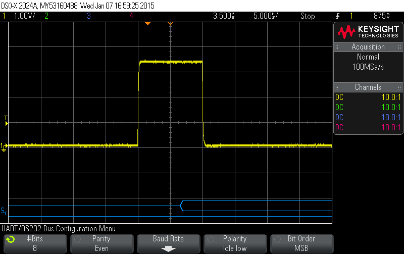
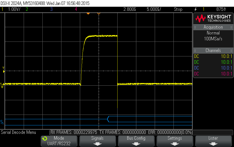
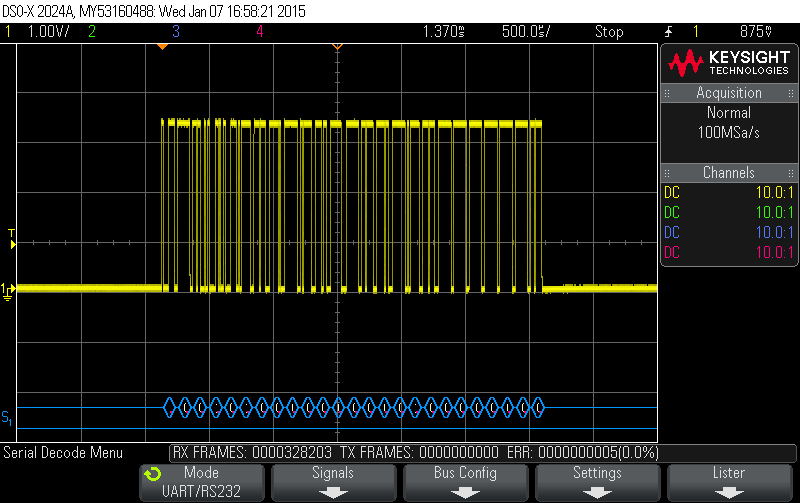
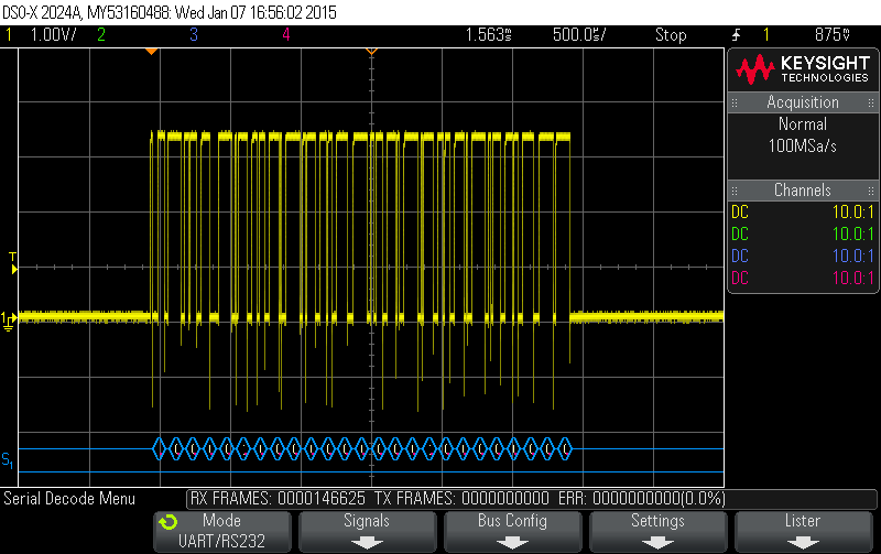
The attached images show the difference between a Futaba s.bus signal and what we get out of the the lightbridge receiver. Note that signal voltage is not an issue (both are about 3.3v), but that the DJI signal has much slower rise time and more noise. The first two images compare Futaba to DJI for the first bit of the data stream (Futaba first). The second two images show the full packet (Futaba first). In the first image the s.bus UART parameters are shown at the bottom of the screen. Note the completely clean serial decode I'm getting on my oscilloscope. The DJI signal is perfectly good enough, and the voltage level is not an issue. The decoder simply has to manage the noise and slow rise time.
Futaba S.Bus first bit:
DJI Lightbridge S.Bus First Bit:
Futaba S.Bus Signal:
DJI Lightbridge S.Bus Signal:
For those following this so far, the only thing left to know about s.bus is that the first 8-bit byte is a header and the remaining signal represents channel levels from 1 to N with 11 bits per channel (line up the bytes decoded MSB first as shown and cut the bits into 11-bit wide chunks). There is more to a full decoding, of course (not the least is mapping the signal to a PWM pulse width), but
s.bus/DBUS by itself is decoded as a UART with parameters shown in the first image.
Probably a lot here of little interest to many, but hopefully these details can help out someone trying to work through this as I am. So far, on the ground side, I have the Lightbridge working with 14 channels out of the Futaba T14SG (setting the trainer port to 16 channels which results in 12 channels + the two "digital" channels). A little decoding/encoding gets the 14 channels out of the radio and into a form the lightbridge ground unit can understand. On the air side, I have a decoder that extracts those 14 channels for use with a WKM controller and gimbal (an A2 and HD gimbal would be good to go I assume, but that's not what I'm using). I'm still working out a few things, but this looks to be a viable solution for my purposes (single-operator setup that can benefit from two more channels).

