nicwilke
Active Member
Oh I get it, we are all wrong about this, I'll tell DJI, STK, ACS, Ultramedia, Cineflex, Bob Nettman and John Doyle that we don't need to worry about newtons third law, all we have to do a stick a brake on each axis so it cant move and then everything will be stable relative to the base it is sitting on. Yeah thats a really cool idea. PID algorithms are not needed as they only have negligible effect ( well there's a few thousand hrs. down the drain for a start). We don't need to worry about vibration attenuation because it cant move Woopee what a great solution you have there. I would keep that to yourself though or everybody will be doing it. I guess the only thing that you did fail was to read all of the previous analysis posts. I don't suppose it occurred to you that a heavy camera does not actually move, it is the surrounding camera mount etc. that does the moving during stabilization with all camera mounts not just PH.
Oh well that livens up my otherwise boring day:tennis: Thank God there's a pub opposite
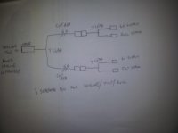
So does damping effect the resolution or not?
")