X8 Design Study

Simspeed

Member
Hello to All:

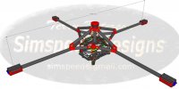
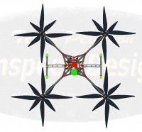
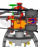
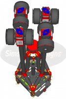
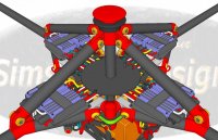
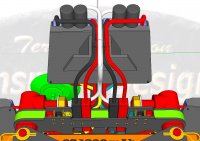
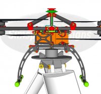
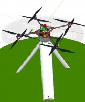
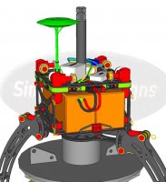
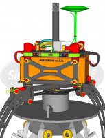
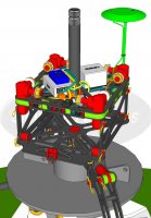
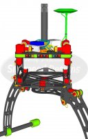
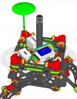
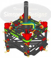
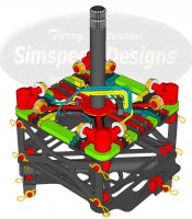
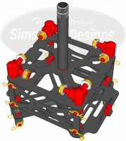
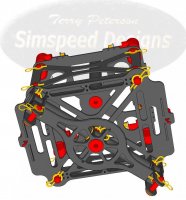
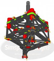
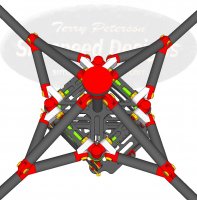
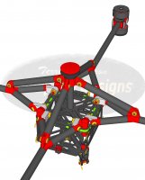
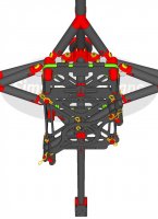
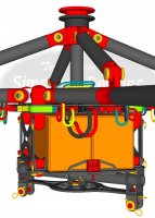
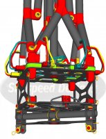
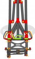
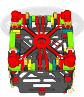
This is my first post so wish me luck....:nevreness:. I am new to the industry but have somewhat ambitious plans to incorporate a multi-rotor of my design into a unique business model that I am pursuing. In the process of creating my design, I have studied much of what is posted here at MultiRotorForums.com. I decided to post some drawings of my design, which pulls from many current ideas of others, in hopes that those experienced souls who regularly share their experiences, here might find time to critique what you see, and offer helpful suggestions how to improve the design... or root out whatever flaws you notice.

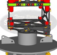
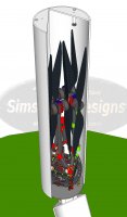
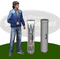
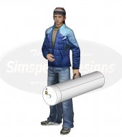
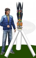
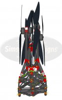
The reason I chose to design-build rather than buy a more common offering, has to do with packaging and portability more so than trying to improve on commercial equipment that already works well but doesn't fit the business model I have in mind. Ultimately, I hope to develop my business idea into a franchise model; and for that, the uniqueness of the multi-rotor design I'm showing here will be well suited. Regardless of my end use for the equipment, what I'm hoping to learn here is whether or not the design I am proposing is in your practical experience worthy of further development or not.

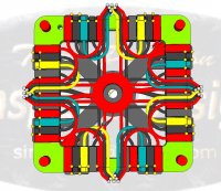
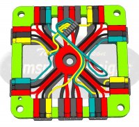
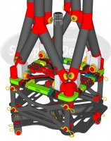
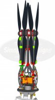
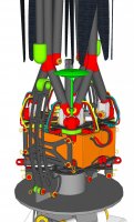
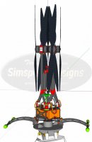
Hopefully these first uploaded images will be suitable for your detailed review. Please keep in mind this is my first venture into the craft of multi-rotor design. I do have practical experience in race car chassis fabrication and project development so I am reasonably comfortable in turning the final design into a working prototype. Please feel free to question or critique any or all that you see. Thanks for your help and advice...TP

View attachment 17131View attachment 17132View attachment 17133View attachment 17134View attachment 17135View attachment 17136View attachment 17137View attachment 17138View attachment 17139View attachment 17140View attachment 17141View attachment 17142View attachment 17143View attachment 17144View attachment 17145View attachment 17146View attachment 17147View attachment 17148View attachment 17149View attachment 17150View attachment 17151View attachment 17152View attachment 17153View attachment 17154View attachment 17155View attachment 17156View attachment 17157View attachment 17158View attachment 17159View attachment 17160
 

Attachments

  • FF.01.JPG
    FF.01.JPG
    77.3 KB · Views: 366
  • FF.02.11.jpg
    FF.02.11.jpg
    132.9 KB · Views: 400
  • FF.02.12.jpg
    FF.02.12.jpg
    136.9 KB · Views: 359
  • FF.02.14.jpg
    FF.02.14.jpg
    146.5 KB · Views: 355
  • FF.02.15.jpg
    FF.02.15.jpg
    126.8 KB · Views: 329
  • FF.03.02.JPG
    FF.03.02.JPG
    136.2 KB · Views: 353
  • FF.03.01.JPG
    FF.03.01.JPG
    116.8 KB · Views: 356
  • FF.05.jpg
    FF.05.jpg
    110.2 KB · Views: 351
  • FF.06.jpg
    FF.06.jpg
    135.2 KB · Views: 369
  • FF.08.jpg
    FF.08.jpg
    139.5 KB · Views: 348
  • FF.09.jpg
    FF.09.jpg
    136 KB · Views: 381
  • FF.10.jpg
    FF.10.jpg
    137.7 KB · Views: 359
  • FF.11.jpg
    FF.11.jpg
    136.1 KB · Views: 384
  • FF.12.jpg
    FF.12.jpg
    136.7 KB · Views: 383
  • FF.13.jpg
    FF.13.jpg
    124 KB · Views: 372
  • FF.14.jpg
    FF.14.jpg
    115.4 KB · Views: 390
  • FF.15.jpg
    FF.15.jpg
    114.7 KB · Views: 348
  • FF.17.jpg
    FF.17.jpg
    125.7 KB · Views: 346
  • FF.18.jpg
    FF.18.jpg
    137.5 KB · Views: 385
  • FF.19.jpg
    FF.19.jpg
    139 KB · Views: 367
  • FF.20.jpg
    FF.20.jpg
    140.3 KB · Views: 322
  • FF.21.jpg
    FF.21.jpg
    136.3 KB · Views: 258
  • FF.22.JPG
    FF.22.JPG
    142.2 KB · Views: 289
  • FF.23.JPG
    FF.23.JPG
    143 KB · Views: 351
  • FF.24.jpg
    FF.24.jpg
    109 KB · Views: 458
  • FF.25.jpg
    FF.25.jpg
    133.6 KB · Views: 391
  • FF.26.jpg
    FF.26.jpg
    137.3 KB · Views: 289
  • FF.27.jpg
    FF.27.jpg
    135.6 KB · Views: 374
  • FF.29.jpg
    FF.29.jpg
    139.3 KB · Views: 329
  • FF.30.jpg
    FF.30.jpg
    134.4 KB · Views: 305
Last edited by a moderator:

SoCal Blur

Member
Very interesting concept - the portability aspect. After studying your drawings I do have a question. Are they to scale? I noticed in drawing 5 that the center rod that connects to the support arms that pull the main arms up into the folded position is very long...about 3 times the height of the body. In drawing 6 with the arms deployed, the center rod appears to be a lot shorter and should be protruding past the bottom of the body if the length in drawing 5 is accurate.
 

Simspeed

Member
Very interesting concept - the portability aspect. After studying your drawings I do have a question. Are they to scale? I noticed in drawing 5 that the center rod that connects to the support arms that pull the main arms up into the folded position is very long...about 3 times the height of the body. In drawing 6 with the arms deployed, the center rod appears to be a lot shorter and should be protruding past the bottom of the body if the length in drawing 5 is accurate.

Hi SoCal....thanks for you comment and question. Yes, everything is to scale pulled from Mfg. dimensions of all the non-fabricated items. The center rod runs from the second frame plate (power plate) up through the top plate. It is bolted to the power plate and does not move as the arms fold and unfold. the support arms are swivel bolted to the quick release mechanism that catches and locks in place when the arms are unfolded and extended out. When the quick release locking plate is pulled, the mount and support arms extend up leaving the center rod below. The interlocking of support arms and quick release mechanism is what keeps everything in alignment. The quick release is something I've used often when mounting race car steering wheels. Very light and strong. Thanks again. (drawing #20 shows a good illustration of the quick release/center rod arrangement).
 
Last edited by a moderator:

yeehaanow

Member
Very cool models. I like the design.
If you can give specs like weight and some general measurements, it would help.
My first thought is that if the arms fold up for transport, what prevents them from folding up during flight?
 

Simspeed

Member
Hi Yeehaanow...thanks for the comment and question. Structural question first....when the arms are folded down into flight position the quick release latches to the splined center post around the recessed area. The quick release is a common item used in almost all race car chassis construction. When it locks, the arms and center section where the pivot mounts are located become one structural component that can not fold or move in either direction up or down. It is a very solid, and structurally sound design. Second....the diagonal dimension between motor centers is 1055mm as seen in the drawing below. These drawings illustrate 28" and an 18" prop layouts shown in comparison. Weights I calculated from published material density and volume figures that the 3D cad program generates for each drawing component. The bare frame including arms, motor mounts, power distribution ring and wiring, center plate with Anderson connectors, battery box assembly, lower gimbal mounts, and all locking pins calculates to 1882g. The landing gear weighs 275g complete with magnetic latching solenoids. The motors I designed with are FoxTech W6135 and they total 1904g. Wiring is 171g, 2 6s 12000 mAh batteries are 3152g, and flight controls are 392g. AUW less payload should be somewhere in the neighborhood of 7.77 Kg. Thanks...TP

View attachment 17161View attachment 17165View attachment 17162View attachment 17163View attachment 17164
 

Attachments

  • FF.56.jpg
    FF.56.jpg
    113 KB · Views: 334
  • FF.58.JPG
    FF.58.JPG
    137.8 KB · Views: 303
  • FF.59.JPG
    FF.59.JPG
    138.6 KB · Views: 495
  • FF.60.JPG
    FF.60.JPG
    98.8 KB · Views: 300
  • FF.35.JPG
    FF.35.JPG
    97.5 KB · Views: 352

Carapau

Tek care, lambs ont road, MRF Moderator
It seems that the ESCs are right by the motors, is that correct? If so ESCs will require a lot of extra capacitors as most ESCs do not like being far from the battery- normallly no more than about 20cm from battery terminal (not the end of the battery leads ie where the battery leads attach to the battery cells) to ESC. Cool idea though.
 

Simspeed

Member
Hi Carapau...thanks for the insight. I had some concern about that too based on comments I've read here and elsewhere. I've seen them located all over the place in lots of different designs....it does look like most of the big lifters do have them closer to the power distribution board. In this design I've tried to minimize wherever possible and near the motors was the most logical placement choice. I may need to rethink that and provide another frame section between the power plate and the top plate to locate the ESCs closer to the PDB. Thanks again Carapau.

Has anyone had a bad experience with the ESCs this far out on the booms like I'm showing here? Thanks.

View attachment 17166View attachment 17167
 

Attachments

  • FF.04.jpg
    FF.04.jpg
    136.2 KB · Views: 260
  • FF.21.jpg
    FF.21.jpg
    136.3 KB · Views: 347
Last edited by a moderator:


Simspeed

Member
Looks very similar to this:
best regards
Ferdinand

HA! Yes Ferdinandk....I took great inspiration from this frame design from Klappfixx that you've been working with. I liked his idea so much that I have attempted to improve upon it with greater simplicity of construction and packaging. If you don't mind would you share the weight of the frame and components like the battery box and the retractable landing gear that was added? What have your experiences with this frame been like? I see that you too mounted the ESCs out on the arms...just not all the way to the motors as I have shown. Moving them inboard in my design is not an easy fix. I may well have to see what is necessary as SoCal suggested to add capacitors so I can use the motor location. Thanks for your post....TP
 
Last edited by a moderator:

Bartman

Welcome to MultiRotorForums.com!!
interesting design, make the tube into a backpack with straps and it could be autolaunched (opens, assembly and power up automatically when a remote switch is flipped by the carrier person) from above the carriers'a head without him/her needing to touch anything. that would be pretty trick.

regarding the ESC locations, conventional wisdom on the internet claims inductance kills ESC's and that wire runs from batteries to ESC's should be as short as possible. Castle's Capacitor packs only allow for an additional 6 inches or so. however, I've mounted ESC's at the motors and have been flying like that with no ill effects. Haven't done crazy hours or really heavy lifts on hot days so can't claim to be all knowing on the subject but have wondered where the limit is if it's really out there.

nice design, but then again, they're all nice!
 

Simspeed

Member
Hi Holger...thanks for your feedback. Considering the size and weight of ESCs like the Hobbywing Platinum-70A Ferdinanda used on the Klappfixx frame machine above, relocating them to the center section of the design I'm working on requires a major overhaul. It's doable of course, but I'd rather not complicate the design further by adding another tier to the center section if I can help it.

My intended use for the machine doesn't require long flight times that require 28" blades and U8 type motors, and the large heavy ESCs that go along with them....but I would like to be able to mount those components as a option for different uses of the machine that others might choose to fly. The motor location is ideas for those purposes if I can learn as SoCal suggest how to apply capacitors to solve the problem. Any recommendations for ESCs to use with the FoxTech W6135's and 18" blades? That combination seems more suitable to support the business use I am planning. Thanks...TP
 

Simspeed

Member
LOL Bartman.... Inspector Gadget to the rescue huh? A back strap could be useful for location hikes. I'll have to give that some serious thought.

I'll look into Castle capacitor packs and see if they would improve the situation here. These arms are pretty long...have you run ESCs that far out on any of your machines? Thanks...TP.
 

Simspeed

Member
You can add capacitors to the ESC to allow for longer cable length between the ESC and batteries.

Hi SoCal....Bartman mentioned the Castle capacitor packs as a possible aid. Have you use those? If not, what other applications could you suggest. Thanks...TP
 

Simspeed

Member
I came up with a solution to the ESC location issue that I think works well. I was able to dimensionally fit the Hobbywing Platinum-70A style ESCs to the base of the arms without having to add another tier to the frame. Complete rewiring needed to accommodate them but thats the benefit of design drawings at early stages of development. I've mounted them in a simple 3D printable fixture that slips into the V notch of the arm and then screws down to the hinge housing by drilling and tapping a couple of bolt holes. Any thoughts? Thanks...TP

View attachment 17178View attachment 17179View attachment 17180View attachment 17181View attachment 17182
 

Attachments

  • FF.61.jpg
    FF.61.jpg
    144.3 KB · Views: 318
  • FF.62.JPG
    FF.62.JPG
    121.2 KB · Views: 323
  • FF.63.JPG
    FF.63.JPG
    63.4 KB · Views: 334
  • FF.64.JPG
    FF.64.JPG
    96.2 KB · Views: 321
  • FF.65.jpg
    FF.65.jpg
    110.1 KB · Views: 332
Last edited by a moderator:


Simspeed

Member
Thanks SoCal....good info to have. Hopefully the new mounting location for the ESCs should remedy the problem. I appreciate the help. TP
 

yeehaanow

Member
I came up with a solution to the ESC location issue that I think works well. I was able to dimensionally fit the Hobbywing Platinum-70A style ESCs to the base of the arms without having to add another tier to the frame. Complete rewiring needed to accommodate them but thats the benefit of design drawings at early stages of development. I've mounted them in a simple 3D printable fixture that slips into the V notch of the arm and then screws down to the hinge housing by drilling and tapping a couple of bolt holes. Any thoughts? Thanks...TP

View attachment 21246View attachment 21247View attachment 21248View attachment 21249View attachment 21250

The thing that strikes me when I look at this is that the wires could take a lot of abuse, and possibly get pulled perpendicular to their attach points. It might be a non-issue, however, it looks like the ESC wires first go to the center hub, then to the esc's? Why not just go straight out the arm?
Another thought is that the holes in the tube where the wires enter, is it stronger to put that hole on the side or top or bottom...? Ideally it would enter in the tube end opening so you don't need a hole, I think. I saw someone feed the wires through and drilled three separate small holes for the wires to exit on a cinestar once. These carbon tubes a pretty fragile and that hole could be a point that starts to fracture over time.
 

Simspeed

Member
The thing that strikes me when I look at this is that the wires could take a lot of abuse, and possibly get pulled perpendicular to their attach points. It might be a non-issue, however, it looks like the ESC wires first go to the center hub, then to the esc's? Why not just go straight out the arm?
Another thought is that the holes in the tube where the wires enter, is it stronger to put that hole on the side or top or bottom...? Ideally it would enter in the tube end opening so you don't need a hole, I think. I saw someone feed the wires through and drilled three separate small holes for the wires to exit on a cinestar once. These carbon tubes a pretty fragile and that hole could be a point that starts to fracture over time.

Hi Tim...thanks for your comments. Drawing wire runs are not easy, especially in tight quarters like this. I've shown these simply for illustration purposes to get an idea how the components will fit and where the leads will run. In actual installation the wires will be loomed and clipped to the frame so they are secure and manageable. Proper loops will be added to prevent wires from being pulled or stretched when the arms are folded up for transportation. Good catch!

I located the ESCs this way for two reasons. First I want all components to be plugged for easy and quick removal. The Anderson power plugs I'm showing are excellent devices in that they provide solid connection and can be pin locked to keep them from becoming accidentally unplugged. I'm showing brass spring pins that install through the FC plates to lock the Anderson plugs together. To remove you simply pinch the end of the pin together and push up and pull out of the plate. In this drawing you can see the pinch pin points protruding from the bottom of the power plate.

attachment.php


Here you can also see the battery wires that lead to the ESCs. I had to turn the battery end of the ESC out away from the center section to allow for clearance for the flight control modules when the arms are folded up for storage. Turned out to be a good thing because it allows for easy connection of the battery leads to the ESCs at the Anderson plugs. The white FC wires that run to the I/O unit are not shown...but they too will plug in at the I/O board for individual removal.

View attachment 17192

Here you can see the wires that come from the motor side of the ESC and how they are looped back to the Anderson plugs inside the PDB. The motor leads from the arms plug in to these plugs on the outside edge of the PDB frame section.
View attachment 17193
Here is the original PDB wiring loom where the ESCs were located out on the arms next to the motors. Quite a different arrangement. The large red ring in the middle is the positive power ring and the black ring below (not seen) is the negative power ring. These will be solid copper with a plastic insulation spacer between. Each ring will be insulation coated and sealed once all the wiring is soldered in place. The center support tube for the arm locking mechanism runs through the middle and bolts from below.
View attachment 17194View attachment 17195
The wiring holes for the arms as shown here, are drilled through the FC tube and the aluminum hinge clevis after the epoxy bonding between the two has cured. So the tube itself is not carrying all the stress of the penetration. The edge will be filed and sealed with dope to capture the sharp edges of the FC and alum. You can see in the x-ray view how the clevis inserts up the FC tube and where the drill hole is relatively located.

This is the only access to the wire run inside the tubes because of the solid rod ends on each tube. The Y fitting in the middle of the arms and the swivel end fitting at the motors are the only hollow fittings to allow wire runs to get to the motors.

Thanks...TP
 

Attachments

  • FF.73.JPG
    FF.73.JPG
    145.4 KB · Views: 270
  • FF.43.2.jpg
    FF.43.2.jpg
    116 KB · Views: 306
  • FF.29.jpg
    FF.29.jpg
    139.3 KB · Views: 376
  • FF.74.JPG
    FF.74.JPG
    66.2 KB · Views: 272
Last edited by a moderator:

Top