Shelipso
Member
Hi guys,
I am investigating the size and arrangements of propellers on a X8 setup. My setting will be around 5 to 6 kg and will have 3508 or 3510 size motors with 14 to 15 inch propellers. This is my first X8 but I have a couple of quads and a Mirkokopter Octo which is getting too old now.
Reading through various forums, it was generally recommended to use a larger propeller with a smaller pitch on the upper motor and a smaller propeller with a larger pitch on the lower motor. To achieve the best combination, bench top testing is the way to go but to reduce the costs and better understand the pros and cons of various arrangements, I decided to do some finite element model testing using Solidworks Flow Simulation. Being a numerical modeller at work, this was also a cross between my job and my hobby. I have to say that as a structural engineer, aerodynamics is not my area of expertise so this is by no means a scientific study by an expert!
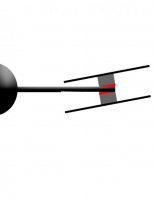
I am testing a 15x5 propeller very similar to Tarot 15x5 carbon fibre ones. Link of the 3d model is below (Credit to mohammad of grabcad community). The file showed to be a good model and is a near true representation of the propellers I am planning to use.
https://grabcad.com/library/propeller-15x5-cw-and-ccw
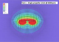
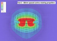
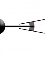
I have so far tested 5 settings. (1) Single propeller rotating at 8200 rpm, (2) Two co-direction propellers spaced at 80mm rotating at 8200rpm and (3) two contra rotating propellers rotating at the same rpm. Case 4 and 5 were variations of case 3 with difference spacing between the propellers.
Using ecalc and based on running a DJI 3508 415 motor at its optimum efficiency on a 6 cell battery (Linked here) I estimated the 8200 rpm to be the base for the tests.
http://ecalc.ch/xcoptercalc.php?ecalc&lang=en&cooling=1.75&rotornumber=4&config=1&weight=2000&calc=sum&elevation=500&airtemp=25&qnh=1013&batteries=lipo_8000mah_-_65/100c&chargestate=0&s=6&p=1&esc=max_30a&motor=dji&type=22|3508-415&gear=1&propeller=carbon-fold-prop&proptwist=0&diameter=15&pitch=5&blades=2
The initial test results were very interesting and I am hoping to get your views and practical experience before I spend more time with this.
Using a single propeller, I am getting a thrust of about 940grams (very close to ecalc number of about 950). I basically tweaked the setting and mesh to calibrate my model against ecalc thrust estimates.
Two propellers rotating at the same direction is giving a thrust of about 1500 grams (30% loss of thrust).
When the propellers are running in contra direction, I am getting an increased thrust of about 2000grams. That is even more than twice!
Being an un-calibrated model, the absolute numbers are not important. What is interesting is that efficiency gain of contra rotating props at the right distance.
I also tested the Contra rotating arrangement for 60 and 100mm space between the motors. 60 showed slightly less and 100 showed slightly more total thrust.
Images below show some output plots. Visually reviewing the flow patterns, the contra rotating prop arrangement is very efficient in creating a uniform downdrift, much better than the two other tested scenarios. It also creates less turbulence. It will be also less impacted by objects around and the potentially the body of the multi rotor than single arrangement or co rotating arrangements.
I understand that as the tests are done at a fixed rpm, they are not necessarily representative of the power efficiency of the arrangements, i.e. the lower motor on a contra arrangements may require more ampere to get to the same rpm. In the contra tests, I noted that the lower motor contributes more to the lift (at the same rpm). This could be very well one reason to use a smaller propeller on the lower motor and balance the load on the motor and perhaps improve the yaw stability and attitude.
I would like to test some more scenarios using a smaller propeller on the lower motor. Before that, I thought to share the results and seek your views and practical experience on similar arrangements.
View attachment 22984 View attachment 22985 View attachment 22986
I am investigating the size and arrangements of propellers on a X8 setup. My setting will be around 5 to 6 kg and will have 3508 or 3510 size motors with 14 to 15 inch propellers. This is my first X8 but I have a couple of quads and a Mirkokopter Octo which is getting too old now.
Reading through various forums, it was generally recommended to use a larger propeller with a smaller pitch on the upper motor and a smaller propeller with a larger pitch on the lower motor. To achieve the best combination, bench top testing is the way to go but to reduce the costs and better understand the pros and cons of various arrangements, I decided to do some finite element model testing using Solidworks Flow Simulation. Being a numerical modeller at work, this was also a cross between my job and my hobby. I have to say that as a structural engineer, aerodynamics is not my area of expertise so this is by no means a scientific study by an expert!
I am testing a 15x5 propeller very similar to Tarot 15x5 carbon fibre ones. Link of the 3d model is below (Credit to mohammad of grabcad community). The file showed to be a good model and is a near true representation of the propellers I am planning to use.
https://grabcad.com/library/propeller-15x5-cw-and-ccw
I have so far tested 5 settings. (1) Single propeller rotating at 8200 rpm, (2) Two co-direction propellers spaced at 80mm rotating at 8200rpm and (3) two contra rotating propellers rotating at the same rpm. Case 4 and 5 were variations of case 3 with difference spacing between the propellers.
Using ecalc and based on running a DJI 3508 415 motor at its optimum efficiency on a 6 cell battery (Linked here) I estimated the 8200 rpm to be the base for the tests.
http://ecalc.ch/xcoptercalc.php?ecalc&lang=en&cooling=1.75&rotornumber=4&config=1&weight=2000&calc=sum&elevation=500&airtemp=25&qnh=1013&batteries=lipo_8000mah_-_65/100c&chargestate=0&s=6&p=1&esc=max_30a&motor=dji&type=22|3508-415&gear=1&propeller=carbon-fold-prop&proptwist=0&diameter=15&pitch=5&blades=2
The initial test results were very interesting and I am hoping to get your views and practical experience before I spend more time with this.
Using a single propeller, I am getting a thrust of about 940grams (very close to ecalc number of about 950). I basically tweaked the setting and mesh to calibrate my model against ecalc thrust estimates.
Two propellers rotating at the same direction is giving a thrust of about 1500 grams (30% loss of thrust).
When the propellers are running in contra direction, I am getting an increased thrust of about 2000grams. That is even more than twice!
Being an un-calibrated model, the absolute numbers are not important. What is interesting is that efficiency gain of contra rotating props at the right distance.
I also tested the Contra rotating arrangement for 60 and 100mm space between the motors. 60 showed slightly less and 100 showed slightly more total thrust.
Images below show some output plots. Visually reviewing the flow patterns, the contra rotating prop arrangement is very efficient in creating a uniform downdrift, much better than the two other tested scenarios. It also creates less turbulence. It will be also less impacted by objects around and the potentially the body of the multi rotor than single arrangement or co rotating arrangements.
I understand that as the tests are done at a fixed rpm, they are not necessarily representative of the power efficiency of the arrangements, i.e. the lower motor on a contra arrangements may require more ampere to get to the same rpm. In the contra tests, I noted that the lower motor contributes more to the lift (at the same rpm). This could be very well one reason to use a smaller propeller on the lower motor and balance the load on the motor and perhaps improve the yaw stability and attitude.
I would like to test some more scenarios using a smaller propeller on the lower motor. Before that, I thought to share the results and seek your views and practical experience on similar arrangements.
View attachment 22984 View attachment 22985 View attachment 22986

")