Wiring Schema G-Lock BLD 3 axis

Droider

Drone Enthusiast
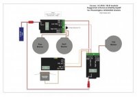
So here is the wiring schema for the Carvec G-LOCK and BLD drivers for a 3 axis set up.

More to come for other set ups

PDF download
View attachment 16622

attachment.php
 

Attachments

  • Carvec Reg.pdf
    77.4 KB · Views: 423
  • Carvec Reg.jpg
    Carvec Reg.jpg
    13.4 KB · Views: 330
Last edited by a moderator:

tombrown1

Member
Wait a sec. I thought g lock was supposed to do 3 axis from 1 radian. What am I missing here?

Also, have you had any success with it?
 

Droider

Drone Enthusiast
The G-LOCK converted radian `DOES' do three axis servos. The schema is for the brushless conversion.

Dave
 

jes1111

Active Member
I think tombrown's confusion is in the diagram - it shows 1 G-Lock Radian (bottom left) and 2 BLD (BrushLess Driver) modules (top left and bottom right). Each BLD can drive up to two motors, hence the two modules. Each G-Lock Radian can measure/control up to three axes.


Droider

Drone Enthusiast
I think tombrown's confusion is in the diagram - it shows 1 G-Lock Radian (bottom left) and 2 BLD (BrushLess Driver) modules (top left and bottom right). Each BLD can drive up to two motors, hence the two modules. Each G-Lock Radian can measure/control up to three axes.

Nice one jes. I drew it how I was installing it on the gimbal. so Radain under camera tray, one BLD next to tilt motor and one up top as close to roll and pan as I could get it.

Guess it may have been better just drawn in a line.


Dave
 

Top