Thoughts on making my power distribution

Gunter

Draganflyer X4
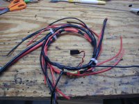
I am busy making my power distribution ring from batteries to esc's. I plan to make it so that I can use either 1 or 2 batteries, so a parallel connection.

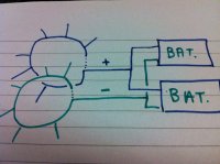
I just don't know if I need to make an open ring, or closed. Should I make it like the diagram, or should I close the loop as I have shown with dotted lines?

Thanks,

Gunter.

View attachment 1255
 

Attachments

  • IMG_0473.JPG
    IMG_0473.JPG
    114.6 KB · Views: 372


jes1111

Active Member
I seem to remember someone saying (perhaps in Boris's thread on his PH gimbal problems?) that you should leave them open - something to do with magnetism ;)
 

Bartman

Welcome to MultiRotorForums.com!!
I forget who it was but someone commented during my Okto build that the negative side of the power ring should not be a closed loop. I can't confirm or deny the validity of it but I opened mine up just in case. I left the positive side closed.
Bartman
 

BorisS

Drone Enthusiast
Im my eyes the abuse mark board just makes sense. Much lighter than any wire dist solution and if you are worried about the current is can take just use two. Another positive thing about it, you will have soldering pads free so if you need an additional output just solder some additional wires on. Clean and fast.

( edit: and yes that was the topic negative should not be closed, cant confirm it, but did it with the first dist ring i had before i switch to the abuse mark board and reduce the weight by 80 gram. )

And its do much fun painting it afterwards with liquid tape :) love this stuff would bath in it, hope it dosent turn out to be a fetish
 
Last edited by a moderator:


jes1111

Active Member
PCB distribution boards are okay for small machines, but I'd be very cautious on a heavy-lifter. The only one I've seen that actually quotes its current capacity is the PhotoshipOne unit - and it's low! A heavy lifter can easily pull 200-300A at full throttle. That sort of current (even for a short time) requires some very heavy-duty pathways. Resistance rises (exponentially) with temperature, so if your distribution board starts to heat up it can quickly get itself into a "run away" condition: 300A won't just melt 2oz. copper - it'll vaporize it!


BorisS

Drone Enthusiast
japp i was always wondering how the MK Dist borad does it with these small pads for soldering on the Lipos and now some use it in a Skyjib with 8 plettis. At the moment i have no problem with the abuse mark board on my WKM hexa with axi 2820, but i will install a second board each board handling 3 motors. Krleas said he tested the abuse mark board with 120 A and had not probs.

Ken did i get this right abuse mark is the Timecop aka jean claude van damme guy from rc groups ?

@Jes1111 no chance concerning the picture I am to shy :)
 

ovdt

Member
PCB distribution boards are okay for small machines, but I'd be very cautious on a heavy-lifter. The only one I've seen that actually quotes its current capacity is the PhotoshipOne unit - and it's low! A heavy lifter can easily pull 200-300A at full throttle. That sort of current (even for a short time) requires some very heavy-duty pathways. Resistance rises (exponentially) with temperature, so if your distribution board starts to heat up it can quickly get itself into a "run away" condition: 300A won't just melt 2oz. copper - it'll vaporize it!

Hello jes,

Do you have any recommendation for heavy lifters? The only solution is a star cable which weights 200 grams?


Gunter

Draganflyer X4
Well, at the moment I have 10 gauge Turnigy silicone cable. I don't mind doing it with this instead of a board, due to the fact that I have already bought the cable, and I don't have space for the board! Dave has also suggested I leave the loop open, so that's what I will do...

I will get the soldering iron out later tonight :)

Thanks for the help guys,

Gunter.
 

Bartman

Welcome to MultiRotorForums.com!!
View attachment 1261

Gunter
The photo is from my last Okto build. The ESC's didn't work well enough for my purposes with the MK electronics so I've since changed it over to an MK XL power board but this is what my power loop looked like for the ESC's. Main loops are 10 ga and the branches for the ESC power are 16. If the picture doesn't show it, I opened up the negative side so it wasn't a closed circle.
Bart
 

Attachments

  • P1010024.jpg
    P1010024.jpg
    146.3 KB · Views: 318

Gunter

Draganflyer X4
Gunter
The photo is from my last Okto build. The ESC's didn't work well enough for my purposes with the MK electronics so I've since changed it over to an MK XL power board but this is what my power loop looked like for the ESC's. Main loops are 10 ga and the branches for the ESC power are 16. If the picture doesn't show it, I opened up the negative side so it wasn't a closed circle.
Bart

Thanks Bart, that's exactly what I had in mind. So it's just the negative loop that's open? Can the positive be left open as well? Would it do any harm?

I'll post some pictures later tonight when I've had a crack at it!
 

Bartman

Welcome to MultiRotorForums.com!!
Thanks Bart, that's exactly what I had in mind. So it's just the negative loop that's open? Can the positive be left open as well? Would it do any harm?

I'll post some pictures later tonight when I've had a crack at it!

don't know. can't imagine it would do any harm.


Top