S800 foldable GPS mount

So here's my only concern, and why I think we are talking multiple layers here...
You said you got some sparks when you applied power. If all that you are doing is connecti two wires that were previously connected, you would not have got sparks. The sparks were due to you shorting two wires that previously were not connected. I think it's going to end up being more than just connecting thee lanes, but that just my opinion. :(
 

ChrisViperM

Active Member
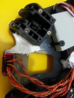
This is what I would do: stick some cello-tape over the drilled hole and the circuit (bottom side), than fill in some good epoxy from the top-side into the hole and let it cure. Pull the cello-tape off and your bottom-side will be even and repaired. On the thin broken circuit lane you could get away with a small solder blob (make sure it's absolutely clean), with the two bigger lanes you will need rather 18 AWG or 20 AWG (just to be sure). Once finished, cover the whole thing with silicone or hot-melt glue. I would not use that hole again for the GPS mast, since this is a "repair area" and potentially weak. The center plate will vibrate, and because the GPS puck is on a mast, this will amplify the vibrations right to the point where the hinged mast-mount is connected to the frame....not a good combination. On my picture you can see the frame-holes covered by some strong plastic and super-glue...that will never come off, so you could do the same with any frame-hole and mount your mast there.


Good luck...


Chris
 

ChrisViperM

Active Member
So here's my only concern, and why I think we are talking multiple layers here...
You said you got some sparks when you applied power. If all that you are doing is connecti two wires that were previously connected, you would not have got sparks. The sparks were due to you shorting two wires that previously were not connected. I think it's going to end up being more than just connecting thee lanes, but that just my opinion. :(

I am also not sure about the frame being a multi-layer circuit-board, but it's impossible to find out without sanding the plate down micron by micron. I suspect it's a single-layer board, since there is enough space and manufacturing double-layer boards is a lot more expensive. Looking at the edges of the board makes me believe it's one solid piece.....worst thing what can happen after the repair is that the copter is not working because another (invisible) lane is broken, but it won't create another short or sparks. In that case there is only one option left: Buying a new plate...but trying to repair won't hurt anything.


Chris
 

Agreed... Try to fix and hope it works.
For those wondering, even though saidquad and I tried to work out a ship and repair solution, he is in a place right now where shipping is not easily doable. Lets hope his repairs work and he's flying soon.
 

saidquad

Member
Thank you Chris and ProPilotWannaBe. I was not able to perform the soldering today. I am going to follow the advice of Chris reg. the repair procedure and let you know about the result. I have also strong feeling that the plate is single layer. I did try to scratch a bit deeper around the hole to see if I reach another layer of circuit lanes but nothing such appeared. I guess the reason of the spark when I connected the power was because I had not fastened the hinged mast-mount completely and it was kind of loose. And maybe it made a short cut between the copper plate on the top-side of the top-plate and the circuit on the button-side of the top-plate.
 

saidquad

Member
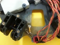
Just a little update. I am not good at soldering. I did not succeed to solder wires to does tiny little circuit lanes so I flattened a gold connector and soldered it to different parts. Then I checked the connection by voltmeter and it indicated that the circuit is connected. I found that this particular part of the circuit is connected to the signal wire of motor NO.5. Since it is a signal wire I guess it is not supposed to handle high amps current and may be my ugly soldering will do the job (but as ProPilotWannaBe said why I got the spark then!?). Before soldering I did fill the hole with epoxy as Chris advised and after soldering I covered the area with some sort of silicone. Now I am waiting for the silicone to dry out and I think I would be able to test the system on the weekend. Sorry the second picture is not sharp.

View attachment 13255

View attachment 13256
 

Attachments

  • topboardsolder.jpg
    topboardsolder.jpg
    124.6 KB · Views: 312
  • topboardsilicone.jpg
    topboardsilicone.jpg
    107.4 KB · Views: 302
Last edited by a moderator:

ChrisViperM

Active Member
heheheheh....that's the wildest soldering I ever saw....but if it works, who really cares ???

I hope you checkt if the soldering is solid.....


Chris


saidquad

Member
Update: I did the test fly today. S800, Retracts, Evo arms, IMU v2+ damping kit, BT LED, Z15, Nex7, FPV cam + immersionrc videolink, DGI video link for zen, IOSD, maxamps 10900mah, firmware 5.24, DJI suggested gains => Total weight 7200g. A little wind (I don’t know how much). Lift up in GPS mode. First battery just hovering around three meters above the ground to check if anything fails during the flight. Rock solid for about 8 minutes and thirty second until each cell was 3.7v onload. No oscillations. I did not film because I was in an area which filming was not allowed. So I don’t know if there would be any vibrations on the film, but I could not see any vibration on the z15. Second and third lipo pack went to moving the bird around a little bit in GPS and ATTI mode with almost the same results.
I would like to thank ChrisViperM and ProPilotWannaBe for their advice and assistance in this reg.
No mysterious behaviors except some yaw drift which I don’t know where it has come from. I mean when I yaw left, the bird rotates on a circle instead of rotating on its z axis. The coordination of COG is exactly x= 0, y= 0, z= -2. GPS is located 4cm forward from COG which is set to x=4cm in the software, 6 cm to the left of COG which is y=-6 in the software and 22 cm above COG which is z=-22 in the software.
 
Last edited by a moderator:

Congrats! Well done! I'm glad you didn't let a few surprise sparks a couple weeks ago keep you from flying!
As for the yaw/rotation, you checked exactly the first thing I would have suggested: GPS position. Check also the IMU position just to cover all bases.
 

saidquad

Member
Thank you ProPilotWannaBe. IMU is located on the new stand which comes with the damping kit. It is 20 cm behind the COG set to x=-20 in the software, right on the y axis set to y=0 cm in the software and 2 cm above the COG set to z=-2 on the software.
one thing I forgot to tell about calibrating the GPS and compass. In the manual it is stated that after calibration is successful the LED keeps white for 3 second and then will exit. For me it was purple for three seconds and went off. No red flashing which would mean unsuccessful calibration.
 

ChrisViperM

Active Member
That's great news...... :tennis:

Try to re-calibrate the compass....sometimes that helps.

wish you crash-free flight......


Chris


saidquad

Member
I wonder now that I am using the damping kit and I get much less vibration on the landing skid why not mounting GPS somewhere on the landing gear to avoid vibration? wouldn't it be better. I say this because I could obviously see that the GPS stick is vibrating a lot and maybe that was the cause of the yaw drift. another thing may be the way I calibrate the compass. When I calibrate, I rotate the MR around myself. So the MR rotates around me not me around Mr. yet another thing since I do the calibration mostly alone. First I trigger the switch from GPS to Manual and back 10 times and when the blue LED lights then I lift up the MR and start the calibration process. It is difficult to lift S800 and flip the switch on tx at the same time.
 

I wonder now that I am using the damping kit and I get much less vibration on the landing skid why not mounting GPS somewhere on the landing gear to avoid vibration? wouldn't it be better. I say this because I could obviously see that the GPS stick is vibrating a lot and maybe that was the cause of the yaw drift. another thing may be the way I calibrate the compass. When I calibrate, I rotate the MR around myself. So the MR rotates around me not me around Mr. yet another thing since I do the calibration mostly alone. First I trigger the switch from GPS to Manual and back 10 times and when the blue LED lights then I lift up the MR and start the calibration process. It is difficult to lift S800 and flip the switch on tx at the same time.
For what it's worth, I do the calibration process the same way as you do.
As for the GPS, the only danger of the vibrating GPS is if it's enough to make it come loose in flight. The vibration itself doesn't affect GPS position of compass or its campass function either.


Top