Motopreserve
Drone Enthusiast
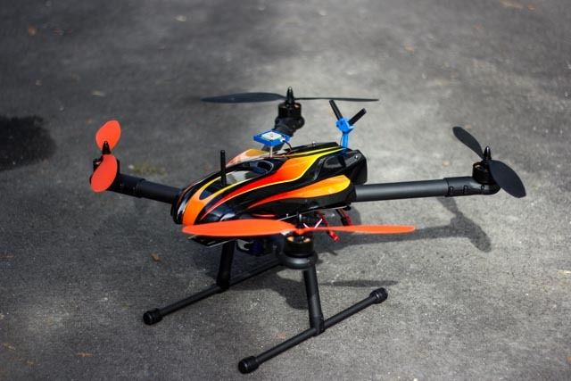
TTRobotix Super Hornet X650 Build and Review sponsored by HobbyRecreationProducts.com.
View attachment 24232
Occasionally you get an opportunity to test something that is outside your comfort zone. Anyone who knows me will tell you that I like to tinker with things…. A lot! Motorcycles, 3D printers, multirotors… You name it; I like to build it. Designing functional builds that work for my needs is what excites me, so you can imagine that most of my projects are DIY, and not chosen in kit form. But sometimes Multirotor Forums asks me to review a product that takes some of the DIY out of the equation, and although I am always willing, I must admit to a certain amount of skepticism. Add to that the recent upsurge in multirotor offerings by a multitude of new (and previously unheard of) companies, and I typically ignore these ‘latest, greatest’ kit products…
So with that said, it's even more exciting when a product that raises my skepticism radar ends up proving me wrong. This was the case when a box arrived on the doorstep with a frame and power/propulsion kit from TTRobotix (Thunder Tiger).
I was unfamiliar with TTRobotix, but after doing a little research, it seems they not only have a history of manufacturing RC air products, but also have some rather cool underwater and road vehicles as well. Their recent focus seems to be capturing video – with 2 new multirotors just released into the market: The Ghost and the Super Hornet X650.
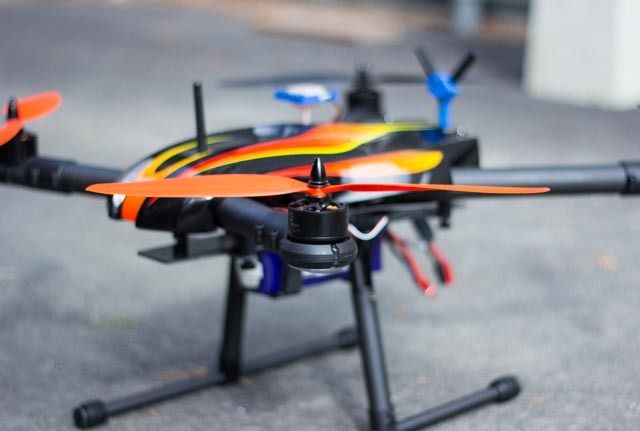
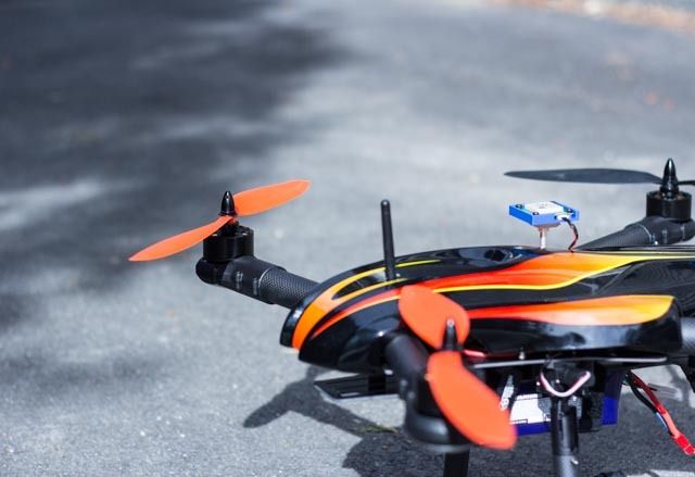
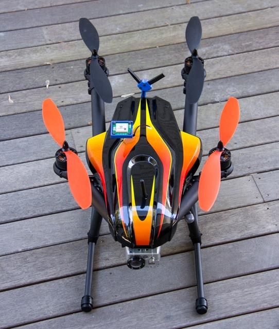
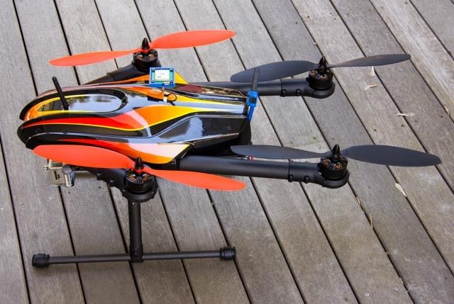
This review will focus on the Super Hornet. Many will find the basic design familiar, with similarities to the Sky Hero Spyder. TTRobotix is offering this asymmetrical folding frame in 2 configurations: frame only, or full ARF kit including motors, ESCs, props, retractable landing gear and a canopy. The only thing missing from the kit is a flight controller (FC), but apparently TTRobotix make an FC called the Dragon.
The basic specs are as follows:
· Quadcopter (convertible to X8)
· 650mm size platform
· (4x) 41x14 stator size, 340kv motors
· 30A OPTO ESCs
· Retractable landing gear
· 14” props
· Integrated PDB
· Suggested Battery: 6S
· AUW (frame, motor, esc etc.): 2.47kg
· Additional Payload: 730g
· Predicted Hover time: 18 minutes
Opening the box…
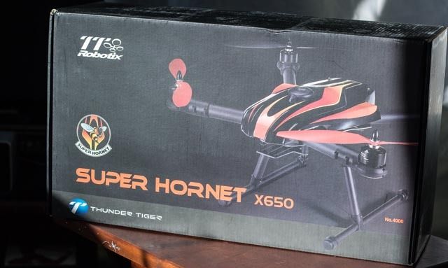
The first thing you’ll notice before opening the box, is how heavy it is. I have to admit that I typically think of a “pre-configured” kit as being less substantial, but here again, I was proven wrong. Based on the weight, whatever was in the box seemed like it was going to be solid.
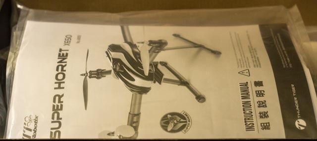
Upon cracking the box, the first welcomed sign was a manual sitting right on top. Maybe it’s my age, but I have grown weary of having to read through instructions on the computer screen. When a product price crosses a certain threshold, I feel the manufacturer should include a printed copy of how it works. Here, TTRobotix made me a happy camper.
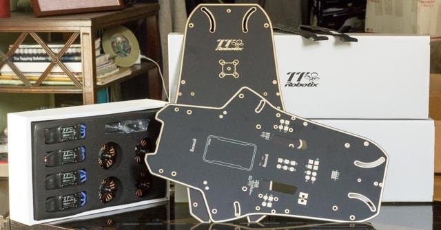
Under the manual and some protective plastic you’ll find the colorful canopy, the frame plates, a foam insert holding the motors and ESCs, and 2 small white boxes. Tucked away in these white boxes, individually wrapped and presented in an orderly fashion, are the carbon fiber booms, motor mounts, hardware and various other parts. The directions seemed fairly straight forward, with diagrams showing the placement of all parts and hardware.
Time to dig in…
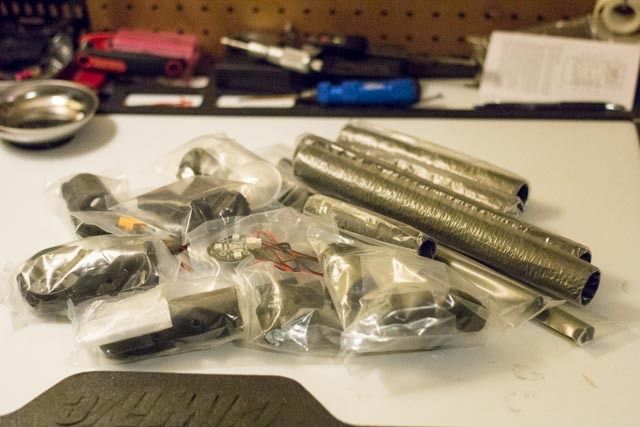
The manual has a parts list on the top of each build section, so I laid all the parts on the bench to make sure that everything listed was here. Once the inventory was checked, I followed the simple instructions, assembling the four complete booms.
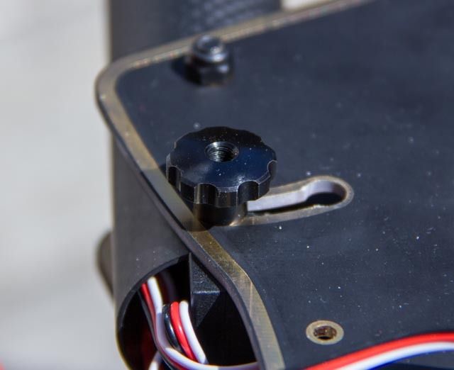
This frame is asymmetrical, so it’s important to note the different parts appropriate for the front and back. Each boom mechanism consists of the 30mm boom itself, a motor mount with included LED (protected by a clear plastic housing), the ESC tucked inside the boom, and of course the motor. Kudos to TTRobotix for delivering some nice quality carbon fiber booms, with no splinters to be seen on the end cuts. The 4014 340kv motors are TTRobotix in-house brand, and seem solid and fit. The motor mounts are made of molded plastic, with nut-shaped recesses that hold the Nyloc, This is a welcome design, but please note that the nuts need to be gently pressed into place with some pliers. My typical method of pulling nuts into place with a bolt from below, did not work. It’s a tight fit, which I’m sure will prove beneficial later. Another nice feature are the matching “keyed” through-holes on the mount and boom, ensuring that the mount will sit level. This is a feature all frames should include, but has sadly been missing on some frames I’ve built.
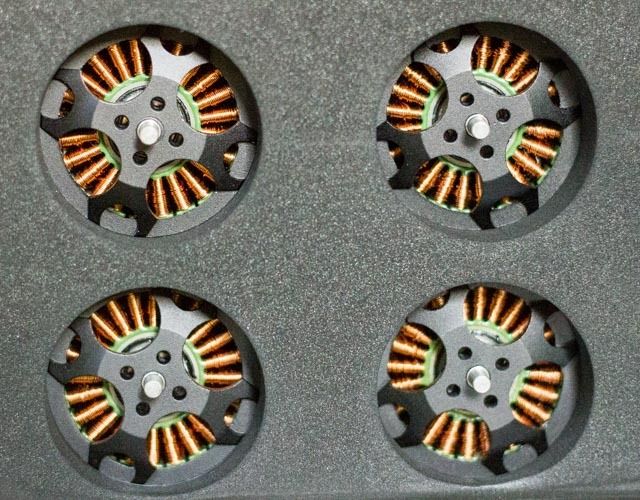
It seemed easiest to assemble the entire motor mount on the bench before slipping it onto the boom. This allows for orderly wiring and better access to the areas for the LEDs. Once finished, routing wires through the 30mm boom is a snap, especially if you have ever tried to snake wiring through thinner arms. One drawback to the included hardware was the length of the motor mount bolts. When finally installing the mounts onto the boom, the bolts proved too short, and could have used a bit more thread. It took some finagling to get the bolts started, and then get each tightened down equally so that they all took hold securely.
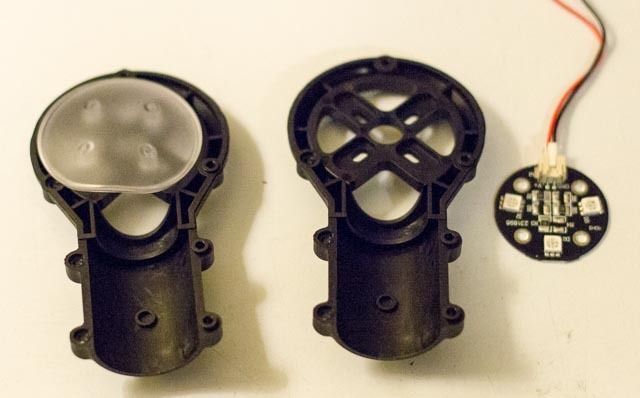
The LEDs fit beneath the motor on the mount, which tucks in with a plastic cover to become one solid unit. The front and back LEDs are shipped with different length wires (and colors obviously) for front and back, but they are not marked, so it’s important to line up the wiring for correct placement, before running them through the boom. With the LEDs in place, the protective plastic cover installed, the whole end of the boom is a tight, neat package.
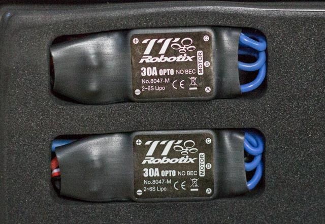
The 30A OPTO ESC is installed inside the boom itself. This installation technique has been a hotly debated (pun intended!), and time will tell if the ESCs suffer from lack of airflow. There was no mention on the ESC, or in the literature whether these are loaded with SimonK or BLHeli firmware. Being proprietary, it’s unclear whether they could be re-flashed. Once the wiring and ESC are inside the boom, a plastic block is installed at the frame end of the boom, with more vertical holes lining up the bolts, which then secure the boom to the frame. Doing a quick mock-up left me wondering if the length of the LED and ESC wiring would be long enough; with the wires barely extending from the frame-end of the boom. I made sure to get the maximum throw from all wires, gently pulling toward the center-plates, making sure not to snag any wires internally. Also, it’s a good idea to put some heat shrink (or electrical tape if you have to) around the ESC/motor bullet connections. Carbon fiber is conductive, and although the bullets arrived with heat-shrink, you don’t want to risk making contact and causing huge headaches later. Another key to any build with ESCs inside the booms: make sure you test the motor direction BEFORE you commit to putting them inside the boom. Trust me, this will save you heartache in the end…
Panic moment: when I installed the first complete motor and mount system to the boom. I tried to spin the motor, and heard an awful scraping sound. Upon closer inspection, a small setscrew was lodged in the windings of the motor. I was able to remove it, and there seemed to be no damage done. Assuming the screw had backed out of the motor, it turned out that it was an unrelated extra screw that found it’s way into the motor at the factory. A quick note for any build: always check the flow and motion of your motor, but SLOWLY. Listening for rubbing or binding can prevent a ruined motor. It’s well worth a few moments of careful inspection while building any kit. The setscrew appeared to have done no damage, so I moved on…
Attachments
Last edited by a moderator:


