Product Review: TTRobotix Super Hornet ARF

Motopreserve

Drone Enthusiast
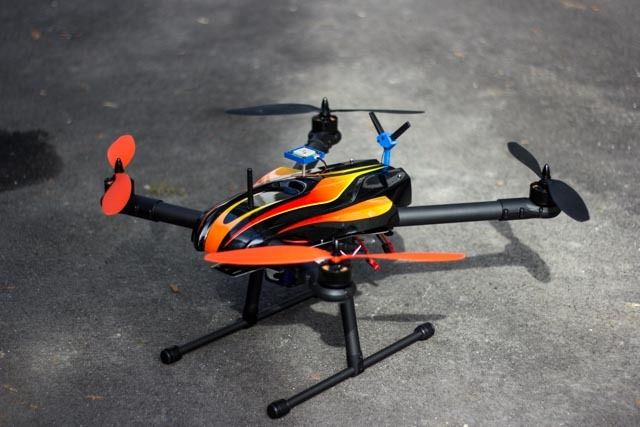


TTRobotix Super Hornet X650 Build and Review sponsored by HobbyRecreationProducts.com.
View attachment 24232

Occasionally you get an opportunity to test something that is outside your comfort zone. Anyone who knows me will tell you that I like to tinker with things…. A lot! Motorcycles, 3D printers, multirotors… You name it; I like to build it. Designing functional builds that work for my needs is what excites me, so you can imagine that most of my projects are DIY, and not chosen in kit form. But sometimes Multirotor Forums asks me to review a product that takes some of the DIY out of the equation, and although I am always willing, I must admit to a certain amount of skepticism. Add to that the recent upsurge in multirotor offerings by a multitude of new (and previously unheard of) companies, and I typically ignore these ‘latest, greatest’ kit products…

So with that said, it's even more exciting when a product that raises my skepticism radar ends up proving me wrong. This was the case when a box arrived on the doorstep with a frame and power/propulsion kit from TTRobotix (Thunder Tiger).

I was unfamiliar with TTRobotix, but after doing a little research, it seems they not only have a history of manufacturing RC air products, but also have some rather cool underwater and road vehicles as well. Their recent focus seems to be capturing video – with 2 new multirotors just released into the market: The Ghost and the Super Hornet X650.

This review will focus on the Super Hornet. Many will find the basic design familiar, with similarities to the Sky Hero Spyder. TTRobotix is offering this asymmetrical folding frame in 2 configurations: frame only, or full ARF kit including motors, ESCs, props, retractable landing gear and a canopy. The only thing missing from the kit is a flight controller (FC), but apparently TTRobotix make an FC called the Dragon.


The basic specs are as follows:

· Quadcopter (convertible to X8)

· 650mm size platform

· (4x) 41x14 stator size, 340kv motors

· 30A OPTO ESCs

· Retractable landing gear

· 14” props

· Integrated PDB

· Suggested Battery: 6S

· AUW (frame, motor, esc etc.): 2.47kg

· Additional Payload: 730g

· Predicted Hover time: 18 minutes


Opening the box…
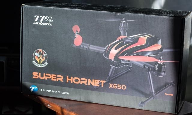


The first thing you’ll notice before opening the box, is how heavy it is. I have to admit that I typically think of a “pre-configured” kit as being less substantial, but here again, I was proven wrong. Based on the weight, whatever was in the box seemed like it was going to be solid.
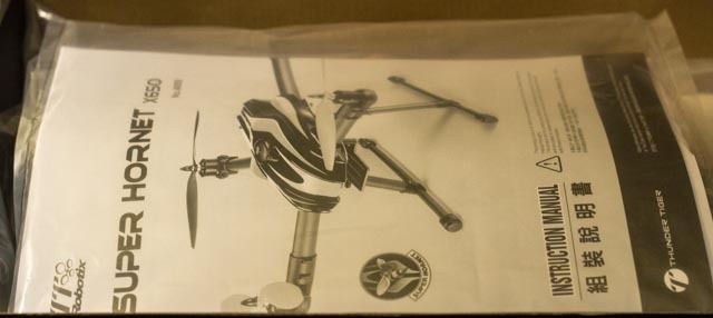


Upon cracking the box, the first welcomed sign was a manual sitting right on top. Maybe it’s my age, but I have grown weary of having to read through instructions on the computer screen. When a product price crosses a certain threshold, I feel the manufacturer should include a printed copy of how it works. Here, TTRobotix made me a happy camper.
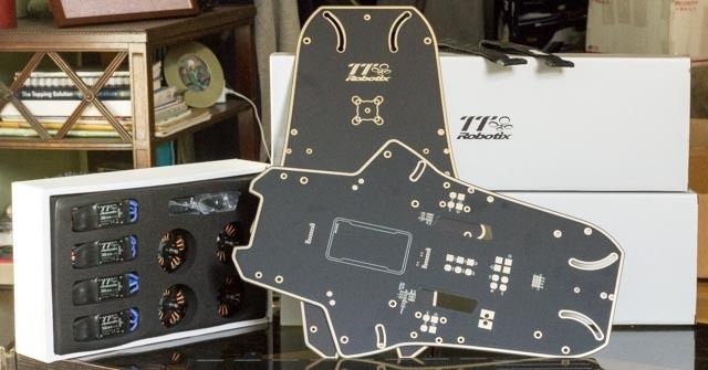


Under the manual and some protective plastic you’ll find the colorful canopy, the frame plates, a foam insert holding the motors and ESCs, and 2 small white boxes. Tucked away in these white boxes, individually wrapped and presented in an orderly fashion, are the carbon fiber booms, motor mounts, hardware and various other parts. The directions seemed fairly straight forward, with diagrams showing the placement of all parts and hardware.


Time to dig in…
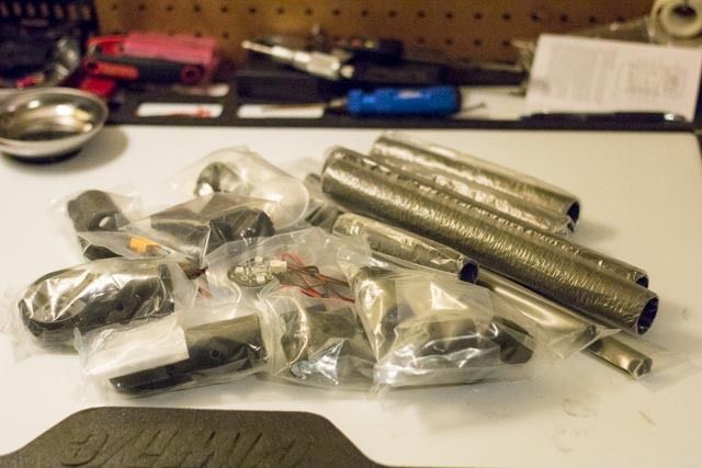


The manual has a parts list on the top of each build section, so I laid all the parts on the bench to make sure that everything listed was here. Once the inventory was checked, I followed the simple instructions, assembling the four complete booms.

This frame is asymmetrical, so it’s important to note the different parts appropriate for the front and back. Each boom mechanism consists of the 30mm boom itself, a motor mount with included LED (protected by a clear plastic housing), the ESC tucked inside the boom, and of course the motor. Kudos to TTRobotix for delivering some nice quality carbon fiber booms, with no splinters to be seen on the end cuts. The 4014 340kv motors are TTRobotix in-house brand, and seem solid and fit. The motor mounts are made of molded plastic, with nut-shaped recesses that hold the Nyloc, This is a welcome design, but please note that the nuts need to be gently pressed into place with some pliers. My typical method of pulling nuts into place with a bolt from below, did not work. It’s a tight fit, which I’m sure will prove beneficial later. Another nice feature are the matching “keyed” through-holes on the mount and boom, ensuring that the mount will sit level. This is a feature all frames should include, but has sadly been missing on some frames I’ve built.
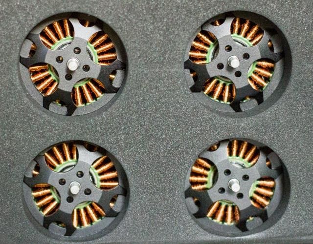


It seemed easiest to assemble the entire motor mount on the bench before slipping it onto the boom. This allows for orderly wiring and better access to the areas for the LEDs. Once finished, routing wires through the 30mm boom is a snap, especially if you have ever tried to snake wiring through thinner arms. One drawback to the included hardware was the length of the motor mount bolts. When finally installing the mounts onto the boom, the bolts proved too short, and could have used a bit more thread. It took some finagling to get the bolts started, and then get each tightened down equally so that they all took hold securely.
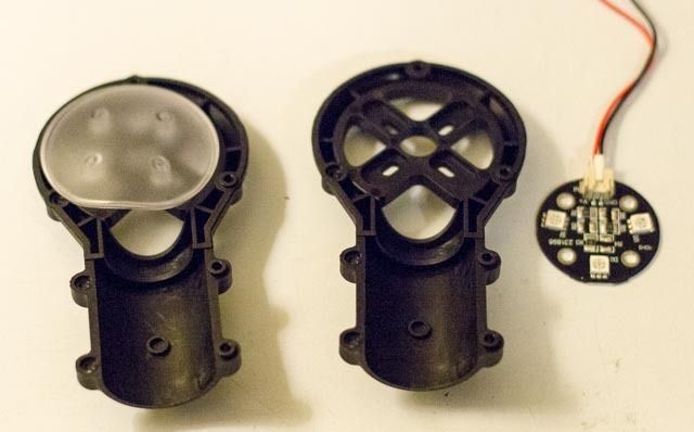


The LEDs fit beneath the motor on the mount, which tucks in with a plastic cover to become one solid unit. The front and back LEDs are shipped with different length wires (and colors obviously) for front and back, but they are not marked, so it’s important to line up the wiring for correct placement, before running them through the boom. With the LEDs in place, the protective plastic cover installed, the whole end of the boom is a tight, neat package.
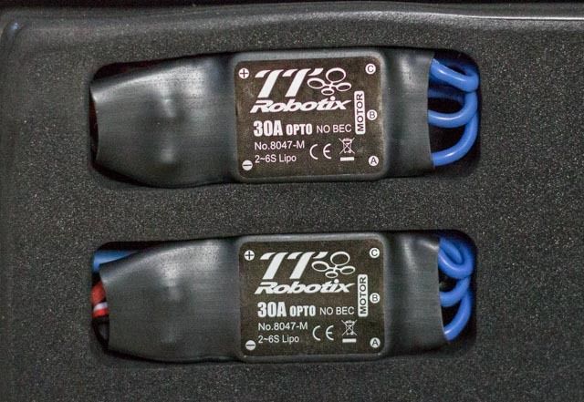


The 30A OPTO ESC is installed inside the boom itself. This installation technique has been a hotly debated (pun intended!), and time will tell if the ESCs suffer from lack of airflow. There was no mention on the ESC, or in the literature whether these are loaded with SimonK or BLHeli firmware. Being proprietary, it’s unclear whether they could be re-flashed. Once the wiring and ESC are inside the boom, a plastic block is installed at the frame end of the boom, with more vertical holes lining up the bolts, which then secure the boom to the frame. Doing a quick mock-up left me wondering if the length of the LED and ESC wiring would be long enough; with the wires barely extending from the frame-end of the boom. I made sure to get the maximum throw from all wires, gently pulling toward the center-plates, making sure not to snag any wires internally. Also, it’s a good idea to put some heat shrink (or electrical tape if you have to) around the ESC/motor bullet connections. Carbon fiber is conductive, and although the bullets arrived with heat-shrink, you don’t want to risk making contact and causing huge headaches later. Another key to any build with ESCs inside the booms: make sure you test the motor direction BEFORE you commit to putting them inside the boom. Trust me, this will save you heartache in the end…

Panic moment: when I installed the first complete motor and mount system to the boom. I tried to spin the motor, and heard an awful scraping sound. Upon closer inspection, a small setscrew was lodged in the windings of the motor. I was able to remove it, and there seemed to be no damage done. Assuming the screw had backed out of the motor, it turned out that it was an unrelated extra screw that found it’s way into the motor at the factory. A quick note for any build: always check the flow and motion of your motor, but SLOWLY. Listening for rubbing or binding can prevent a ruined motor. It’s well worth a few moments of careful inspection while building any kit. The setscrew appeared to have done no damage, so I moved on…
 

Attachments

  • HRP_Logo.png
    HRP_Logo.png
    8.2 KB · Views: 521
Last edited by a moderator:

Motopreserve

Drone Enthusiast
Frame assembly...

With all four boom assemblies complete, time to move on to the frame itself. The Super Hornet consists of two center plates; the lower plate houses the integrated power distribution board (PDB), the top plate for rigidity and protection, with ample room for additional electronics placement. The two main plates are made of G-10, which may not be as sexy as carbon fiber, makes sense for sensitive electronics.


Time to get the PDB soldered up and ready for power…


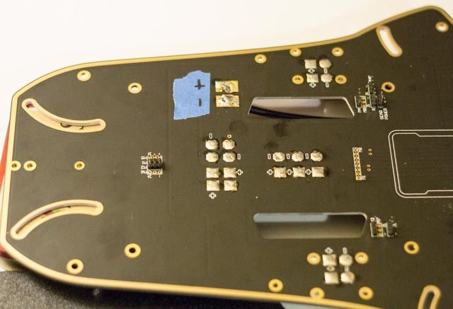
Included with the instruction booklet was a single sheet – the PDB plate photocopied with each contact point labeled clearly. The PDB plate arrived with no connectors installed, or solder on any of the numerous contact pads. I quickly cleaned and tinned all the pads, and laid out the components to be installed. Studying the schematic showed a unique design of contact points for all servo connections to be used on the build, as well as the standard ESC and power connections. There are plenty of additional large solder pads provided for extra power needs, such as video and FPV equipment. Nice touch. The bag of components included 3-pole header pins for servo connections, as well as all mounting hardware to secure the plates together. I soldered the header pins on, making sure to skip the provided points for the 4 additional ESCs, that are included to convert the quad into an X8. The PDB is well thought out, with the servo power and ground lines that internally run to the flight controller removed. This requires making a harness of single servo wire leads if you want to keep the quad neat, but using typical 3-wire servo leads would work here, since the power and ground wires would be “dead” where they connect to the FC.

Another thing to note when building this ARF kit – the ESCs should be re-tinned. I found the solder on the wires to be incomplete (very common), and something worth checking. All connections are laid out well, and fairly easy to access even with the top plate on. The exception to this is the header pins for the retractable landing gear. I had opted to skip installing the retracts until the end – making it easier to work on the frame, on my small bench. This turned out to be an issue when I later had to install the retract servo leads. When the top plate is installed the retract connections are placed in a difficult spot to access. Word to the wise: install the retracts when suggested in the instruction manual!

Once all the prep was complete, I did a test run of the wiring for length. My fear of the ESC and LED wires being too short proved true, and although I was able to get most of them soldered in place with the provided length, it was a VERY tight fit when folding the booms. I extended a couple of the LED leads for safe measure – because the folding mechanism is one of the key components of this frame, and should not be hindered due to an issue so easily fixed. Once soldered, the integrated PDB makes for a very clean build. I double-checked my work with a continuity tester, making sure none of the servo header pins were crossed or shoddy.


Time to put it all together…

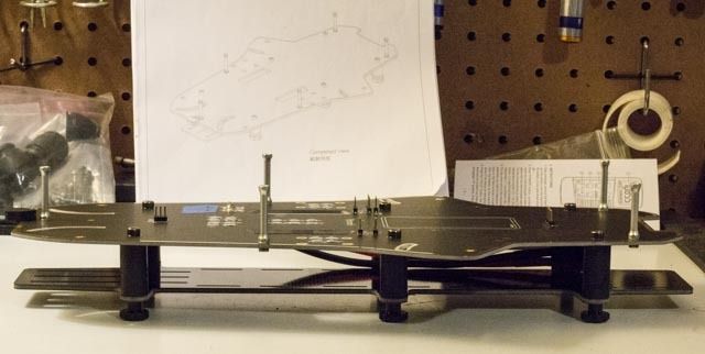
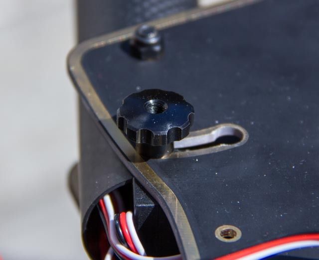
As mentioned earlier, the booms come with pre-drilled holes for keying the placement. This is a welcomed addition to any frame, ensuring proper alignment for level motors. The frame went together quickly with solid standoffs securing the two plates together. A common design, the two plates sandwich the booms, with bolts traveling through the "key" holes for placement. Instead of using nuts or Allen-head fasteners for the top pivoting end of the booms, they are replaced by thumbscrews for easily loosening when folding the frame. The slots which allow the booms to fold are drilled with "rounds" at each end of the travel, allowing for the thumbscrews to settle down into the slot for secure tightening. On any folding frame there is concern for movement in flight – but these recesses seem like a solid solution to keep the booms in place. The only drawback to this design is the fact that if the canopy is used, access to the thumbscrews requires removing the lid. Not a deal breaker, but it might be quicker to have the thumbscrews on the bottom of the frame for easier access.

For many, retractable landing gear is going to be a welcome addition to any build. The Super Hornet retracts consist of the typical components; including aluminum retract servo housing, carbon fiber rods, as well aluminum t-clamp for the landing gear itself. The retracts went together easily, and the components seemed solid and strong. This will be my first build using retracts (how has it gone this long???), and I was encouraged by the apparent strength of the aluminum mounts and carbon fiber rods used for the assembly. The retracts bolt straight onto the bottom frame plate, and I was impressed that there were holes drilled in the top plate to access the bolts from above with an Allen wrench.


The next piece of the puzzle is the 3mm thick carbon fiber “battery tray.” The reason for the quotes, because once installed, I realized that the distance between the lower PDB/frame plate and the tray was not large enough to house any 6S battery I own. The plate mounts to the frame using 6 substantial rubber standoffs, attached using the same style thumbscrews as seen on the folding mechanism. I'm not quite sure what the purpose is for these thumbscrews, but they tighten well, so no harm done. There are convenient slots spaced along the plate for use of the included Velcro battery straps. For my purposes, the batteries will need to be secured to the bottom of the tray. I may mod this design a bit and add thick standoffs to the rubber mounts, allowing room for my current batteries, mounted inside the protection of the plates.

Finally, the props were mounted to the motors. These motors are supplied with the cone-style fasteners, each with right-hand threads. I am not a fan of this style – and it’s wise to replace them with Nyloc nuts for safety. The four supplied props (2 red for the front, 2 black for the rear) seem to be a composite type, not flexible like plastic, but certainly not carbon fiber either.

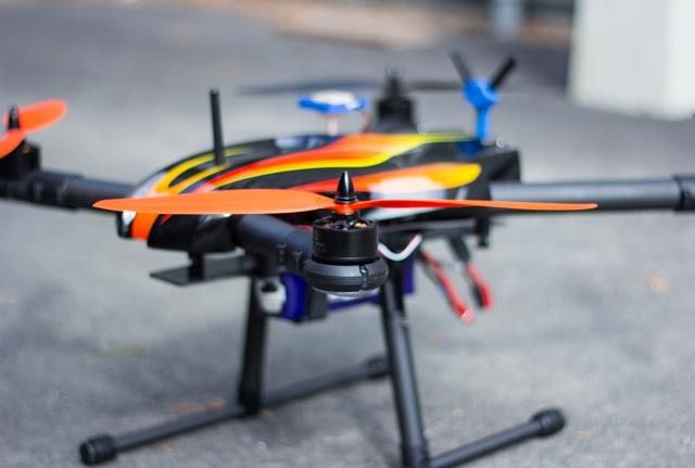
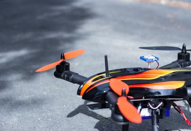
The frame kit now complete, except for the cherry on top… The canopy. It’s a modern looking affair, with pre-painted lines and racing stripes. While pre-painting at the factory saves the hassle of applying decals, I would assume that not everyone has the same taste in cosmetics. The canopy is made of thick fabric-backed plastic (fiberglass?). I needed to cut some holes in the canopy to allow the GPS mount and 3DR radio antennas to emerge from the inner sanctum, and this was easily achieved using an RC body reamer tool, and proved that the canopy should provide a certain amount of resistance to crashes and mishaps.


The lowest plate, meant for securing the batteries, I assume is meant to serve double-duty as a place to mount a gimbal. There is no rail system, nor any holes that seem obvious for mounting. With a prescribed payload of approximately 700 grams, it will be interesting to see what type of camera platform will work best on this system. This additional payload sits right in the middle of the gimbals/cameras that I currently own. A guess: perhaps TTRobotix have a proprietary option that they plan to employ for this frame.

The frame now fully assembled, the retracts were in need of some testing, and having been shipped in the up position, I needed some room on the bench. Unfortunately, the first tests showed one side to be working perfectly, the other to be stuck in the up position. Not exactly helpful for balancing the MR on the bench. I tried to work the retract by hand - but it wasn't budging. I finally disassembled the entire servo and found that the gears were not moving freely. A little bit of finagling and I got the gears free - and assumed I would place it in the down position, and leave it that way for flight testing. Upon getting the servo back together and reinstalled onto he frame - the next test proved successful - and now both retracts were operating as expected.

The total build time for this ARF kit was approximately 3 hours, and that included a few missteps along the way. The clear instructions and layout made for quick assembly, and should be an easy affair for even those new to the hobby. The inclusion of the entire power system will be a welcome option for some, and for those looking to mount their own motors/ESCs, there is a frame-only version.


Stay tuned for the first flight tests and final thoughts...

I had some issues with my flight controller on the first tests in the field, but seem to have them worked out now. Unfortunately the Vermont winter has refused to go away, and weather has not been cooperating. So stay tuned for some flight tests and more thorough real-world assessments will be coming soon.
 
Last edited by a moderator:


Bartman

Welcome to MultiRotorForums.com!!

Motopreserve

Drone Enthusiast
I think I would need to fab a mount for it. Unless there is an included accessory that would interface with the battery tray.

Be interesting to see how this TTRobotix gimbal stacks up against the H3-3D.


Motopreserve

Drone Enthusiast
I think this introductory offer makes this a very compelling option for anyone looking for a neat, compact foldable frame.

Should have some flight tests done by mid-week and posted immediately afterwards.

Stay tuned....
 

Bartman

Welcome to MultiRotorForums.com!!
yes, please post a few pics of it folded and a close up of the mechanicals that make it foldable. :)
 

Motopreserve

Drone Enthusiast
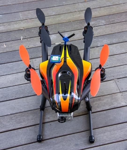
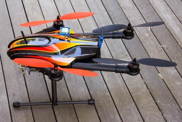
Here are a few shots of the Super Hornet X650 frame in the folded position. The frame measures in at approximately 27" long by 15" wide when folded. Swapping the props out for some that would accept the quick-release prop adapters could cut the size down even more.


Note the locking mechanism for the folding frame in the photo below. The inclusion of the small round recesses at the end of the channel allow for the thumbscrew to settle into the groove, providing some security when tight.


Bartman

Welcome to MultiRotorForums.com!!
that's more compact than i would have guessed given the size of everything
thanks for the photos


Motopreserve

Drone Enthusiast
This frame is very similar to the Sky Hero, as far as I can tell from online only research. Unfortunately, I don't have one to compare and contrast. I will say that I did not have the issues with installing the ESCs into the booms like I read so much about with the Sky Hero.
 

SleepyC

www.AirHeadMedia.com
Looks a lot like a "Sky Hero" quad. Would love to see a comparison between them

I've owned Skyhero quads. They are similar but very different. Sky hero stuff is very highness carbon and the frame plates are held apart by blocks.

The plastic in the Skyhero kits is top notch as well, but you have to pay a pretty price for that quality!
 

Motopreserve

Drone Enthusiast
I'm not sure what "highness carbon" is (SIRI???), but I would say the CF is good quality (although not 2mm walled) and the plastic actually stands up to some heavy tool torque at least. Haven't crashed it yet to test its impact resistance :)

It also seems the center plates on the super hornet might have some more room for extra electronics. The sky hero may have a more eloquent battery storage solution???
 

maxwelltub

Member
I find the skyhero to be an absolute pain in the ass to take apart for maintenance. This looks good having an intergraded pdb.
 

Motopreserve

Drone Enthusiast
The integrated PDB is actually much more complete than others I've used, with servo headers for running the esc wires, retracts etc.

Makes for a pretty tidy setup.
 

Top