Bartman
Welcome to MultiRotorForums.com!!
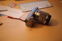
Success!! I found some thinner wire in an A/V cable and was able to get it attached to the solder pads. The pads are so tiny though and the solder paste isn't as strong as regular high-temp solder so the wires popped off over and over until I was able to get them hot glued into place and the cover back on. The shutter button works though and the wires also trigger the shutter so now it just needs a JST plug and a couple of cable ties to anchor it. All in all it was a fairly stressful experience but now I can swap out my T2i with the NEX and use the same wire from the Pico switch to trigger the shutter.
I'm happy to share my experience if anyone else wants to give it a try. A couple of quick notes:
trim the black plastic just outboard of the switch so the wire from the backside of the switch has a spot to tuck into
pre-bend a u-turn in the wire that will solder to the back pad so you don't have to try to bend it after soldering (there's no strength to anything and they pop off!)
grind a small relief hole for the wires to exit the case before soldering the wires. straight ahead from the front corner pad is a good idea as the front corner solder joint is weaker than the back middle joint
Strip a quarter of an inch from each wire and tin the ends with regular solder then trim to have just enough to attach to the pad....turn the iron down (i used 450-500 degrees) before using the soldering paste to attach them
with the wires in place force a tiny amount of hot glue around the wires just where they exit the case to help keep them from breaking off at the joints....too much glue though and you'll get it on the pads making future repair and/or soldering difficult
use a tissue to really get the tip of the soldering iron clean after wiping it on your sponge. little blobs on the tip look like boulders under the magnifying glass
other than that, DJ's guide was very helpful.
Last edited by a moderator:


