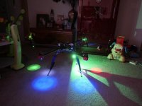
Aeronavics / Droidworx New Build Skyjib 6 Ti with retractable legs

Quinton

Active Member
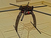
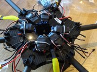
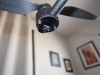
Got the Skyjib 6 Titanium with retractable legs delivered today, and 5 hours later so far so good. (2 Hours seemed to be getting the vibration dampeners fitted into the gear rail bracket)
Total weight so far 1640 grams without power dist board and any electronics/motors etc.

Big thank you so far to Andrew from Multirotorcraft.co.uk who has been a massive help so far, and spent lots of time walking me through what I would require.
(Not to mention he's helping me out with a few bits of soldering on the Distro board)

To think I was almost going to buy an S800 Evo, wouldn't have been half as enjoyable as trying to do it yourself.
Happy so far with part 1, but the manual certainly needs updating for the Skyjib 6 Ti, a lot of guessing (and a few spare parts went on) :nevreness:

View attachment 13770
 

Attachments

  • skyjib6ti.jpg
    skyjib6ti.jpg
    140.9 KB · Views: 421

cbpagent72

Member
Got the Skyjib 6 Titanium with retractable legs delivered today, and 5 hours later so far so good. (2 Hours seemed to be getting the vibration dampeners fitted into the gear rail bracket)
Total weight so far 1640 grams without power dist board and any electronics/motors etc.

Big thank you so far to Andrew from Multirotorcraft.co.uk who has been a massive help so far, and spent lots of time walking me through what I would require.
(Not to mention he's helping me out with a few bits of soldering on the Distro board)

To think I was almost going to buy an S800 Evo, wouldn't have been half as enjoyable as trying to do it yourself.
Happy so far with part 1, but the manual certainly needs updating for the Skyjib 6 Ti, a lot of guessing (and a few spare parts went on) :nevreness:

View attachment 17394

I will be following your build closely as I am also building a SkyJib 6 Ti right now as well. I would love to hear about any unique issues that you encounter.
 

Quinton

Active Member
As you know the manual doesn't look anything like the parts you have, especially the retractable legs, and the crash cage so it is a bit frustrating.
You can see though that things "just fit" they are really well made.
I do have a few parts missing on the crash cage 5 spacers and the washers to go along with them, but am sure I will get that sorted soon.
Now I have put together one, I could do another in half the time, just wish the manual would have been a bit more thorough and up to date.
One thing I would like to ask others is where do they feel the need to use threadlock during the build?
The vibration dampening in the motor boom arms is very impressive.
 

Quinton

Active Member
Going to make a good start today with everything seeing my new soldering iron should arrive later.
Quick question out there for everyone, as I have asked 5 different people and have had five different answers.
Threadlock, where exactly do you use it on the DW build, and is it needed on the screws that go through the booms, that have the split washers (Are the washers sufficient)

Another question, once you use the threadlock how to keep check that it is doing its job, obviously if you tighten it slightly you will be breaking the lock.
And Nyloc nuts, one person I spoke with said that they should only be used once, what are your thoughts on that?
 

cbpagent72

Member
Going to make a good start today with everything seeing my new soldering iron should arrive later.
Quick question out there for everyone, as I have asked 5 different people and have had five different answers.
Threadlock, where exactly do you use it on the DW build, and is it needed on the screws that go through the booms, that have the split washers (Are the washers sufficient)

Another question, once you use the threadlock how to keep check that it is doing its job, obviously if you tighten it slightly you will be breaking the lock.
And Nyloc nuts, one person I spoke with said that they should only be used once, what are your thoughts on that?

I have the exact same question as you. I stay away from using blue thread lock on any nylon stand offs or nuts but I use it on almost all metal nuts and bolts. I don't use red threadlock at all, I have heard too many horror stories about striping bolts trying to get the stuff off and the only real way to do it is heat up the bolt. I believe the locking washers help but I still a little threadlock on them anyway. I would love to hear some of our more experienced forum members chime in and receive their input.
 

Quinton

Active Member
Ok I seem to be getting there, but have a few questions more.
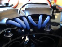
The motor wires already had 3.5mm bullet connectors on, but how long is too long for cables?
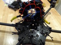
I could take about 6 inches off them all and have them all stuffed in the middle connected to the ESCs a lot more work, or I have each coming out of the boom, turning left then through the large hole as in the picture then up to connect with the ESC bullets, a lot neater but are the cables too long.
Another question is the ESCs, as you can see in the other pictures.
Is it Ok to have the red black and blue cable wires underneath, on the same side as all the power cables, or would I be better coming up above the ESCs (on front) and coming out, I would have very easy access without taking anything apart to the bullet connectors from the ESCs and the Motors, and could easily check if they are connected OK visually.
Hope this makes sense from the pictures.

This setup will actually make it very neat using the 12mm standoffs that come with the frame (longer ones wont be required), and I can fit the Crash Cage, and Dome on easily.
Is there a chance of Interference with the ESC wires being so close to the power cables underneath the board?

View attachment 13998View attachment 13999View attachment 14000
 

Attachments

  • DSC00557.jpg
    DSC00557.jpg
    144.1 KB · Views: 291
  • DSC00558.jpg
    DSC00558.jpg
    142 KB · Views: 375
  • DSC00559.jpg
    DSC00559.jpg
    135 KB · Views: 424

rotorvista

Member
if you plait the motor wires it will shorten the lengths. The T motor ESC's I used have bullet connectors built into them so the motor wires are perfect length after plaiting. I guess you could shorten the wires on the ESC's
 
Last edited by a moderator:

cbpagent72

Member
Quinton,

Your PCB looks very clean with the ESCs attached to the board. Since I am using the Gryphon PCB I have to be creative with the location of the ESCs. I was thinking about using Velcro to secure them to the bottom of the top-plate. I am wondering if Velcro is an acceptable alternative to zip ties?


cbpagent72

Member
Velcro is good for clothing lol:). 3m Dual lock is a better fastener

I guess my question should have been, will there be heat issues if I use Velcro/Dual Lock type fasteners on my ESCs?

Sent from my SPH-L720 using Tapatalk 2
 
Last edited by a moderator:

Quinton

Active Member
Have the ESCs mounted on the first plate, all seems really well except noticed 1 thing which could cause a problem.
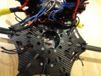
The solder points on the Droidworx PDB, the front left motor if you are in X configuration, seems to be extremely close to one of the built in screws holding the boom arm on.
Has anyone else noticed this?All the other screws are well clear of everything.

View attachment 14023View attachment 14024View attachment 14022
 

Attachments

  • DSC00563.jpg
    DSC00563.jpg
    132.8 KB · Views: 237
  • DSC00564.jpg
    DSC00564.jpg
    146.5 KB · Views: 246
  • solderpoint.jpg
    solderpoint.jpg
    138.7 KB · Views: 245


Quinton

Active Member
they are close, i put hot glue over my solder points. what are you doing about lighting?
Haven't even thought about lighting yet, I'm just concentrating on getting a spinning motor without killing myself :)
Did you use the DW standoffs, 12mm ones, or did you put bigger ones on?


cbpagent72

Member
Have the ESCs mounted on the first plate, all seems really well except noticed 1 thing which could cause a problem.
The solder points on the Droidworx PDB, the front left motor if you are in X configuration, seems to be extremely close to one of the built in screws holding the boom arm on.
Has anyone else noticed this?All the other screws are well clear of everything.

View attachment 17684View attachment 17685View attachment 17683

I noticed the issue with the screws as well.
 

Quinton

Active Member
OK Plugged everything in tonight, and got the motors all working and spinning the right directions.
Never used Wookong-M before, but is it normal to arm motors nothing happens until you put throttle up?
Usually if you arm them then they start to idle?
Also throttle is linked to X3, are there some settings I should be looking at in more detail?


Maverick

Member
OK Plugged everything in tonight, and got the motors all working and spinning the right directions.
Never used Wookong-M before, but is it normal to arm motors nothing happens until you put throttle up?
Usually if you arm them then they start to idle?
Also throttle is linked to X3, are there some settings I should be looking at in more detail?

In the Assistant, change the Motor Idle Speed to a setting higher than what it's at now. It's in the "Motor Mixer" section.


Quinton

Active Member
In the Assistant, change the Motor Idle Speed to a setting higher than what it's at now. It's in the "Motor Mixer" section.

Ok that has fixed it, although Ill keep it at recommended for the motors just to arm without starting.
Thats a bit different to the Naza were recommended starts the motors.

Have the latest firmware installed and everything seems fine.
Have 1 "noisy" motor which I will need to swap out, not sure why its so noisy, all the others are fine.
Can't believe how sensitive the Wookong actually is, I was testing on my kitchen table (don't we all) and was wondering why the motors were going faster/slower even though I wasn't touching the sticks.
Discovered it was actually the vibration of the bad motor going through the table and affecting the FC.
I set a piece of vibration gel under it, and it fixed it immediately, wonder if its worth doing that when I fix it to the machine.

The x3 was set on J3 for some reason (Not used to this Futaba 14SG) usually use the T8FG but its very similar, so just set up my gains on x2 and x3 and now just need to set my Failsafe end points and should be getting there.
Also added the Bluetooth LED and even that seems to work really well with my iphone.

Only thing that isn't working on the PC or the phone is the "motor test"not sure if theres a problem there or not with the latest version?
 

Top