Motopreserve
Drone Enthusiast
Hey folks,
I've had this bench top motor/prop thrust tester project on the back burner for a while, and I want to see if I can button it up tonight. Just want to run the process by you to see if there are any tweaks or fixes before I fire it up. I've been a little frustrated by the lack of info out there on the motors I've purchased, and at worst there has been some manufacturer misinformation about basic values (wrong pole count etc).
I have put the tester together in a basic way with cheap/found parts. I'd like to make sure it's safe and effective, and then maybe I'll make it better/pretty")
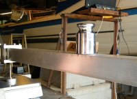
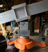
currently I followed designs that create an equilateral triangle (it has some extra space off the end - so maybe it's an Isosceles triangle) out of 2x2" wood, with a separate wood base (1"x3") with "feet" that attaches with a door hinge. The one end rests on a scale (reading in grams), which is level with the base. This leaves the bottom of the triangle perfectly level on a digital leveler.
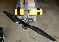
I have a cheap HK-010 power analyzer hooked up between the battery and an electrical block (for easy connections of various components). The block then has outputs to the ESC/motor. The motors will be mounted using a mount that I had lying around from an old build, which is attached securely to the vertical arm. The ESC is driven by a cheap servo tester - which I used to calibrate the ESC throttle settings. I've also flashed the ESC with the latest simonk firmware (June 18, 2014?).
My goal is to get readings for amps and watts being pulled, as well as monitoring voltage for various motor and prop combinations.
QUESTIONS:
1. Is there anything I'm missing? Improvements?
2. Would it be more wise to set up an RX to run the ESC/motor from a radio instead of the servo tester? I have marks for 50% throw! but that hasn't been tested scientifically. Is there a way I should test this with a multimeter?
3. I have the motor mounted facing away from the scale end. So I turned around the prop around (upside down from normal installation on an MR) so that it's facing the scale end. Does this make sense?
Any tips are much appreciated.
Scott


I've had this bench top motor/prop thrust tester project on the back burner for a while, and I want to see if I can button it up tonight. Just want to run the process by you to see if there are any tweaks or fixes before I fire it up. I've been a little frustrated by the lack of info out there on the motors I've purchased, and at worst there has been some manufacturer misinformation about basic values (wrong pole count etc).
I have put the tester together in a basic way with cheap/found parts. I'd like to make sure it's safe and effective, and then maybe I'll make it better/pretty
currently I followed designs that create an equilateral triangle (it has some extra space off the end - so maybe it's an Isosceles triangle) out of 2x2" wood, with a separate wood base (1"x3") with "feet" that attaches with a door hinge. The one end rests on a scale (reading in grams), which is level with the base. This leaves the bottom of the triangle perfectly level on a digital leveler.
I have a cheap HK-010 power analyzer hooked up between the battery and an electrical block (for easy connections of various components). The block then has outputs to the ESC/motor. The motors will be mounted using a mount that I had lying around from an old build, which is attached securely to the vertical arm. The ESC is driven by a cheap servo tester - which I used to calibrate the ESC throttle settings. I've also flashed the ESC with the latest simonk firmware (June 18, 2014?).
My goal is to get readings for amps and watts being pulled, as well as monitoring voltage for various motor and prop combinations.
QUESTIONS:
1. Is there anything I'm missing? Improvements?
2. Would it be more wise to set up an RX to run the ESC/motor from a radio instead of the servo tester? I have marks for 50% throw! but that hasn't been tested scientifically. Is there a way I should test this with a multimeter?
3. I have the motor mounted facing away from the scale end. So I turned around the prop around (upside down from normal installation on an MR) so that it's facing the scale end. Does this make sense?
Any tips are much appreciated.
Scott
Last edited by a moderator: