Gunters NEW hexacopter build

Gunter

Draganflyer X4
Hello Guner,
nice Thread... realy ... but i search for the AfroPowerboard for my CX4!
Where can i order this item ?!
Thx a lot..
Marcell from Germany

Marcell, just do a google search for abusemark, thats the website that sells them.


Regards,

Gunter.
Sent from my iPhone using Tapatalk
 

Gunter

Draganflyer X4
Hi Gunter

Do you know many amps the afropower board can take? Is it good enough for skyjib 8 with wkn, plettenberg 15-20, hobbywing fly fun 40 opto!?

Thanxs

Not sure how many amps I would trust with it. It works fine with my hexa, but it's not lifting a monster load, only 5kg. Try emailing the abusemark website and ask them. I know someone has done this before but can't remember what thread it was.


Regards,

Gunter.
Sent from my iPhone using Tapatalk


BorisS

Drone Enthusiast
hope that helps:

could you please send me a current rating or estimate for your power
distribution board. I am using it happily on one of my hexa now i want to
setup an octo with it but not sure if in an emergency full throttle
situation with a loaded 6kg octo a possible over 100A draw could cause some
issues. I was thinking of putti two boards of yours in parallel each
handling four ESCs.

100A for a short burst should be OK. Buut, if you're really dealing
with these kind of current - it might be better to simply use ex.
12AWG wire and make a power spider with connections for each ESC. No
amount of copper is going to help here. That being said.. the worst it
will do is heat up. If you don't plan to hover @ 100A (that would be
crazy anyway), short bursts will not heat up that much. What AWG wire
do you have going to the board? Just make sure your solder joints are
nice and clean and it should be ok. Also doubling the boards would
work, 3 motors per each and some fat wire to batteries. Depends on
your power distribution really.


-tc
 

Tomstoy2

Member
Don't quote me, but I thought I read it was good to 60a constant. Also, thought I read others were dividing the load between 2 boards to prevent issues.
 

BorisS

Drone Enthusiast
Yeah i don't know, either none of them are really testing them or avoiding a clear statement. If you want to be on the safe side two board is probably better. On the other hand take a look at the thin small soldering pads you have on all the distribution frames for MK Bl Ctrls which makes me wonder and take a look at most OSD Telemetry current sensor extensions that are rated to 100A which don't have a lot of meat in my eyes.

Boris
 

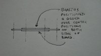
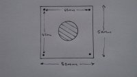
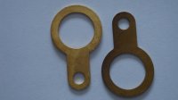
View attachment 3790View attachment 3791View attachment 3792The pictures show an idea that I have been experimenting with to overcome the problems of many amps flowing down fairly thin copper plate to fairly heavy motor loads. The washers are brass banjo washers that have a 'plane' that is 1mm in thickness and 5mm in width. They will easily carry 200-250 amps. Their shape allows them to be glued into a central position either side of a prepaired paxoline board. Typically the lower side could be connected (soldered) to the battery negative while the upper side is coneected to the battery positive. Any other leads from ESCs, etc. could be connected to the appropriate washer anywhere throughout its circuference. I have shown rough drawing of a insulating paxoline board of 50mm x 50mm x 1mm dimensions with prepaired mounting holes of 45mm centre to centre. Of course the course can be cut and prepaired to size of any suitable dimensions. The insulating board weighs 11 grams and the banjos weigh just 8 grams...not too bad for that performance level. An Afro board weighs 13 grams. It would be an improvement to use banjos made from copper but sourcing them is a problem.
 

Attachments

  • DSC01217.jpg
    DSC01217.jpg
    147.1 KB · Views: 292
  • DSC01218.jpg
    DSC01218.jpg
    146.9 KB · Views: 315
  • DSC01219.jpg
    DSC01219.jpg
    145.9 KB · Views: 297

jes1111

Active Member
I'm building a small board to handle eight motors through two BTS555 switches in parallel. Power feed onto the board is from multiple Anderson 45A connectors soldered straight on (1 per battery, up to 4) using their High Current PCB Contacts. The board is a sheet of 1.6mm FR4 with a sheet of 0.5mm copper epoxied to each side then milled/drilled on a CNC as per a normal PCB. Photos when it's complete.
 

Top