Flight times, temperatures and all that

MombasaFlash

Heli's & Tele's bloke
First of all i would get rid of the heavy box that came with the hdmi to sd converter.
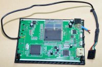
Second the traco power is for powering video link. (pls take notice that it is instaled wrong , the white dot needs to be on right side). On the MC board, they marked it on the wrong side so they got it wrong. We need to change picture but we forget it until someone link it and reminds us of the error.

ABout the extra caps. With high curents it is better have them instaled.

Krleas

Thanks Krleas.

The 5D has composite out and therefore does not need the HDMI converter. I use it with the NEX-5n but I am not madly impressed by the Sony. Sweet camera but poor lenses.

I have been using an Extension PCB to power the downlink. Much simpler to use the traco on its own! Where does the 12v regulated supply emerge on the PDB from that traco?

MikroKopter would do well to tell folks when they introduce a new change/feature on their boards.

Should the four extra caps also be 330uF/35v?
 

krleas

FPV Freak
U didnt understand me, im using hdmi converter too. Just remove metal casing and conectors. The board thickness is 8mm and weignt only 50g.
I added 5V dc/dc convertor and plug directly to powerboard or lipos.

About Caps yes.

View attachment 1830
 

Attachments

  • gh2.jpg
    gh2.jpg
    57.6 KB · Views: 172

MombasaFlash

Heli's & Tele's bloke
I understood fine and yes, the weight (and space) saving by removing the heavy metal box is clear. I just don't plan on using it that much (with the NEX-5n) because the 5D produces better images. I also like the fact that the 5D's weight helps to smooth out the flight.

I had hoped that the NEX-5n would be a weight-saving, worthy and less risky alternative to the 5D. As it is, if I can sort out the AD-8 to carry the 5D without sweating so much, the NEX will go on the small MK Octo - or head off to eBay!

Good idea putting the 5vdc regulator directly on the board.


jes1111

Active Member
You want to change the "charge state" on the battery line to "full". I'm not entirely sure, but I believe that "normal" and "low" exist only to show you how long you'd fly for if you started with partially discharged batteries - odd, therefore, to default to "normal". Anyway - it makes quite a surprising difference to the numbers. It's also worth changing the battery to a high-C (temporarily) so you can see what a really lively pack will do to the numbers (it will dip less under stress so all numbers will be higher).

Also I note that you're using APC SF props, which are somewhat inefficient - changing to APC E props (not sure what pitch they have in 12" size) will improve the numbers. On 4S you've got enough headroom on the motors to run a higher pitch without turning anything red.

Not sure why eCalc is calculating AUW wrong for you - it counts motors, battery, ESCs as "drive", i.e. you need the weight of props, wire, etc. included in your static "excl. drive" weight. Anyway, you got there, so no worries. (Actually, thinking about it, yes - it's a little pessimistic on weights for batteries and ESCs, so that probably accounts for the inaccuracies.)

You've identified one of the things that bugs me about flat 6- and 8-motor setups - you're limited on prop choices unless you remortgage the house and pay Droidworx's price for longer arms - nuts to that!


?

*****

Guest
Two more questions relating to the MK PDB board...

First, and this has been asked before elsewhere but no satisfactory explanation yet, what are these extra capacitor spaces for (labelled C1 - C4) and what value caps should be there?

018.BLctrl.jpg


Second, what is the purpose of the voltage regulator that is shown on RTF PDB's on the Kopterworx shop ...

019.OctoPDB.jpg

double the caps on the board with 680uF (on the empty spaces)


If I am correct. The Traco 12v Regulator supplys a regulated 12v for external use on the Power Distribution board. For instance, If you were using a 4-5 cell lip, the traco would drop that voltage down to only 12v, that way you could run power for your LED's or Video TX off the power distribution ring. Without the Traco, the full 4-5S voltage would go straight into your LED's. Did that answer that question clearly ?
 

MombasaFlash

Heli's & Tele's bloke
That all sounds about right.

I already use two Traco's with two Extension PCB's, one outputting 12v (switched for low battery LED flashing and direct for video) and the other 5v. I was unaware that there is provision for installing a regulator directly on the power distribution board without having to fiddle about with Extension PCB assembly. It is an addition to the PDB that remains unmentioned on the Wiki.


?

*****

Guest
That all sounds about right.

I already use two Traco's with two Extension PCB's, one outputting 12v (switched for low battery LED flashing and direct for video) and the other 5v. I was unaware that there is provision for installing a regulator directly on the power distribution board without having to fiddle about with Extension PCB assembly. It is an addition to the PDB that remains unmentioned on the Wiki.

it is mentioned if you look on the pictures on the wiki.

why do you use 2 extension boards?

1 board had 12 volt out , 9 volt out
and 2 on/off functions if you stay on 4S you can total the load on the extensionboards to 20 amps
if you go above the 4S you need to put a traco onto the extension board.
 

MombasaFlash

Heli's & Tele's bloke
it is mentioned if you look on the pictures on the wiki.

why do you use 2 extension boards?


Really? Where? Can't see the wood for the trees in that wiki.

I use the switched 12v output of Ext.PCB #1 for low battery warning to the LED's and direct 12v out to the downlink. I do not wish to put unnecessary load on the FC 5v supplies so there is a second Ext.PCB with 5v Traco just for the HDMI converter and the High Visibility LED's - which I may get around to installing one day.


MombasaFlash

Heli's & Tele's bloke
Here is a question for those with better knowledge of these things.

Suggestions to avoid the hot cables have been to increase the cable diameter and to use two cables, one for each of two separate packs. The first problem to overcome with this is how to attach such a large amount of copper wire to the rather small pads on the MK Octo PDB. I am thinking to cut away a small section of insulation in the middle of the cable with either end feeding a LiPo pack. At least there will still be only one thickness of cable to attach to the pads.

But then I got to thinking ... and this is the question I want to ask ... even the current 12AWG silicon wire presents more surface area than those PDB solder pads so what advantage can be had by using thicker wire? All that electricity is going to end up at the same bottleneck - the PDB solder pads.

And, whilst I am here, I cannot find 680µf electrolytic capacitors here. The available choice goes from 330µf to 470µf to 1000µf.
 

jes1111

Active Member
When the cables get hot, does the PDB get hot too? I note from an earlier post that your current draw at hover was 66.7 amps, which agrees (more or less) with the eCalc theoretical figures and, as a figure, shouldn't be producing such temperatures. I'm thinking that something else is wrong here - most probably the PDB which, I've heard, is a poor piece of design. The nasty thing about overloading a conductor is that it quickly gets into a runaway condition - as temperature rises so does resistance, which just accelerates the heating. I'm not familiar with MK gear (I looked, I rejected) but I've heard of people "building up" the conductor by soldering thick copper wire along the tracks. I'm no electrical expert, but I recall a scientifically-supported conclusion in a thread on openpilot.org about PDB - that they can work at high currents only if distances are very short. This would seem to correlate with your situation - are the hotter ESCs the ones that are furthest from the battery input point on the PDB? I'd still replace the feed cables with 10AWG or 8 AWG - but I'd also look at either replacing or "reinforcing" the PDB.
 

MombasaFlash

Heli's & Tele's bloke
... are the hotter ESCs the ones that are furthest from the battery input point on the PDB?...

That is an interesting take.

I have no idea if the PDB is getting hot as well and I do not know if the cables are hot for their entire length. BL temperature readings recorded so far indicate they are roughly in pairs i.e. similar temperatures, and going from hottest to coolest the order is 1&2, 3&8, 4&7, 5&6.

Distances from the solder pad to the BL caps, starting with the furthest, are 2&3, 1&4, 5&8, 7&6. Not identical but following a similar pattern.

I might as well try soldering on some heavy duty copper wire between the spare voltage pads top and bottom of the PDB. I so dislike 'Heath Robinson' workarounds.

I have received a few comments here advising changing to 5S LiPo's but now I have just had a response to a direct question on the subject from MK saying that a bigger LiPo will only INCREASE the BL temps.

ECalc says otherwise. So who is right?

My plan of action at the moment is to change one thing at a time, starting with a double, heavier battery cable (if only HobbyKing's 3-day, AKA 9-day, shipping option would arrive). I will keep the Deans and the 4S' and see if there is any significant change. Next to go will be the Deans' in favour of 6mm bullets.

This will all be WITHOUT a camera + mount, and with no extra baggage I want to see a much narrower range of BL temps. If that is the case but the range widens with a camera onboard then the whole mount has to be shufftied around to load the opposite motors. This is all sort of fun, but on the other hand ... it isn't.
 

MombasaFlash

Heli's & Tele's bloke
So, two big fat 10AWG battery cables with 6mm bullets (that are the devil's own job to separate) has taken care of the hot cables and connectors.

Flight data as follows.

1x 4S/5000mah, no camera
Total weight ........... 3855g
Average amps......... 45A
BL temp range ....... 26-43°C
Flight time ............. 07:34 (MKTool low batt. setting 33 : 4S = 13.2v)

2x 4S/5000mah, Sony NEX-5n, HDMI converter and HiSight SLR2
Total weight ........... 4905g
Average amps......... 47A
BL temp range ....... 30-62°C
Flight time ............. 12:46 (MKTool low batt. setting 33 : 4S = 13.2v)

2x 4S/5000mah, Canon 5D mk2, SLR2 ( and HDMI converter because I couldn't be bothered to remove it)
Total weight ........... 5974g (5881g without HDMI converter pcb)
Average amps......... 63A
BL temp range ....... 35-78°C
Flight time ............. 10:30 (MKTool low batt. setting 33 : 4S = 13.2v)

I have a suspicion that my Tx needs recalibrating. Folks have said NEVER use trim, but I only get a steady level hover with negative SUB-trim applied to Pitch, Roll and Yaw, otherwise the AD-8 skittles rapidly off to the left and forward and yaws clockwise - precisely the same with the MK Octo. A quick check in MKTool shows that when sticks are centred those three axes are off by a few digits. Applying sub-trim brings them to ZERO ... AND permits stationary hover. GPS position hold is stable and is NOT affected by this Tx sub-trim. Perhaps because the FC is actually seeing zeros for centre stick readings?

I have a couple of new, unused identical Tx's so I will try one of them to verify the centre stick readings.
 
Last edited by a moderator:


krleas

FPV Freak
Now switch to 5s with 1 batterie 8000mAh 30c.

And u are ready to rock and roll. Flying times arround 10 min and no problems with heating.
 

Top