Pumpkinguy
Member
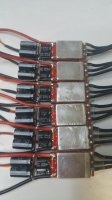
This thread is an oldie but a goodie. I'm thinking about moving my esc location further out for a number of reasons. I did this esc today just as a mock up.
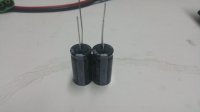
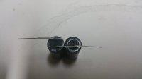
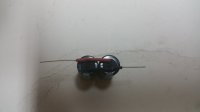
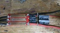
Stock caps are 470uf and these are 1200. Probably way overkill.
1 x 1200uf would fit better and effectively double the stock capicitors. I may go that route.
Stock caps are 470uf and these are 1200. Probably way overkill.
1 x 1200uf would fit better and effectively double the stock capicitors. I may go that route.
")