I did post this diagram some time ago, but the minim OSD wiring was not clear, and the power for the camera gimbal was not indicated. Just check your modules, and the colours of the wires dont seem to be a standard, so one has to look at the individual connections. Also I mentioned that the Video signal wires could be screened, only do this if you have interference on your video. Hope this helps....
You are using an out of date browser. It may not display this or other websites correctly.
You should upgrade or use an alternative browser.
You should upgrade or use an alternative browser.
Complete wiring
- Thread starter Trevcharl
- Start date
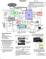
You will need 10 channels on your controller, most controllers can be set up for PPM and 9 & 10 assigned to tilt and roll. (On the controller) Some controllers have LCD screens making it easy to set up like Flysky FS-i6s. To set up the apm you will need mission planner, download and run in windows. APM planner works on Ubuntu.I did post this diagram some time ago, but the minim OSD wiring was not clear, and the power for the camera gimbal was not indicated. Just check your modules, and the colours of the wires dont seem to be a standard, so one has to look at the individual connections. Also I mentioned that the Video signal wires could be screened, only do this if you have interference on your video. Hope this helps....
I did post this diagram some time ago, but the minim OSD wiring was not clear, and the power for the camera gimbal was not indicated. Just check your modules, and the colours of the wires dont seem to be a standard, so one has to look at the individual connections. Also I mentioned that the Video signal wires could be screened, only do this if you have interference on your video. Hope this helps....
Just a quick update....The Minim OSD Mavlink (the one without the extra connections on the side) came with the links for using the same power on both halves, already connected as a PC track. I actually wanted to feed the two halves separately as shown in the diagram, but I reverted to the alternative. the dual row of three connectors, only video in and video out pins are used. The power comes from the APM, connection to the Minim OSD. The smoothed battery voltage is not connected, nor the earth, these connections +5 and ground come from the APM connection. The wifi camera I discovered needs 5v, so I conveniently used a BEC output from an ESC. This could cause interference, but we will see when I have completed the project. If it does cause problems, I will add a 7805 and a cap to drop 3S to 5v just for the camera.