AV200 IDD 360 Pan Kit Assembly Figured Out
Help! I am have an AV200 IDD I bought awhile ago from PhotoHigher. They sent out the IDD gimbal assembled; with a Pan Kit unassembled. The documentation on the assembly of the Pan Kit is not clear to me:
http://photohigher.com/assets/Uploads/AS-013-AV200-IDD-Conversion-Assembly-Instructions.pdf The photos and instructions lack the detail of the previous documents for the standard serveo AV200 (
http://www.quadrocopter.com/assets/templates/quadrocopter/downloads/assembly_AV200-360pan.pdf or this one
http://www.photohigher.com/assets/Uploads/AV200-2360MR-Build-Guide.pdf). I need an exploded view or an illustrated series that shows if the thrust bearing is actually sitting on the second bering on top of the gimbal housing.
I can make educated guesses; but I should not have to with this quality gimbal. Any assistance would be appreciated.
Thanks for the assistance - Cheers!
I answered my own question with the documents above for the old style gimbal and Droider's photos here:
http://www.multirotorforums.com/sho...ss-Gimbal-Controller-amp-Photohigher-AV200IDD.
Sorry if the following is a tad off topic but I feel it is important to record it somewhere; it would have helped me. I will add this in my build thread as well (
http://www.multirotorforums.com/showthread.php?19613-New-Build-HexaCrafter-1100L-Heavy-Lift).
These instructions refer to the following items (from my invoicing):
PhotoHigher: 001-0060 AV200 IDD Standard DroidWorx 360 Pan Kit - NoSkids and 000-1010 AV200 IDD 2 Axes Brushless Gimbal Assembly mounted on the gear rail of DroidWorx (Aeronavics) 4404-0041-XM Landing Gear and Gear Rail Assembly Retractable Ti - Extended. It finishes off with about 3/4 inch (20mm) clearance from the deck.
For a partial list of terms see the original AV200 Pan IDD conversion instructions (
http://photohigher.com/assets/Uploads/AS-013-AV200-IDD-Conversion-Assembly-Instructions.pdf) and the list here -
http://www.quadrocopter.com/assets/templates/quadrocopter/downloads/assembly_AV200-360pan.pdf.
The pan head assembly sequence and abbreviated instructions follow:
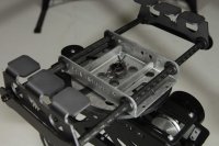
1) Remove the DroidWorx Camera Mounting Bracket Assembly from the Gear Rail Assembly. Remove the DroidWorx Camera Mounting Bracket from the rails. Later this will be replaced by the modified PhotoHigher Gimbal Mounting Bracket with gimbal. In the PhotoHigher 360 Pan Kit remove the two aluminum DroidWorx adapter plates (one has PHOTOHIGHER carved into it and other is shaped similarly but nests inside the larger plate. The smaller plate fits perpendicularly inside the larger plate; screw them together with 3mm nuts and bolts in the preexisting holes – this unit is the PhotoHigher Gimbal Mounting Bracket. Fit the grommets into the holes in the Gimbal Mounting Bracket. Put this aside.
2) Push the Bearing + Flange up into Bottom Bearing Bracket (bracket tabs point down - push the Bearing + Flange hard, use a flat surface like a small square piece of wood and push evenly and firmly). Screw the bracket into the gimbal using the mounting holes. Push the second Bearing + Flange onto the center hole on the top of the gimbal (push firmly and evenly down or turn the gimbal over and push on the same surface used previously). Insert the Pan Axis Bearing Spacer (small aluminum cylinder) between bracket and the inside of the top of the gimbal (a tight fit) it will rest between both Bearing + Flanges. Push the Pan Shaft up from the bottom of the Bottom Bearing Bracket, from inside the gimbal housing, and through the top of the gimbal and the top Bearing + Flange. Temporarily hold the shaft in place with tape at the top of the gimbal.
3) Locate the Pan Motor Assembly and maneuver it into the top of the gimbal – screw it loosely into the cut out at the top of the gimbal. Screw the V Pulley onto the top of the Shaft on the Pan Motor Assembly. Later the assembly, shaft or pulley will need to be adjusted as well as the pressure that the V Pulley exerts on the V Disc.
4) Carefully remove the tape holding the shaft and hold it up in place from the bottom. Place the Thrust Bearing (wide ring of needle bearings with a hole in the center) over the Pan Shaft on top of the gimbal housing. At this point the bearing may be lightly lubricated. The shallow aluminum cylinder (Thrust Bearing Cap) has an indentation, this fits over the Pan Shaft and rests on the Thrust Bearing. The V Disc has a recess that fits over the Thrust Bearing Cap. The V Disc Spacer fits on top of the V Disc.
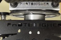
5) Get the Gimbal Mounting Bracket (step one above) and place it on the V Disc Spacer. Place the aluminum washer over the end of the shaft and place the lock nut on the shaft, tighten just enough to hold everything firmly and place the Spring Pin through the holes in the shaft.
6) Make sure the V Pulley and V Disc are even and snug just enough to run freely. If they need adjusting disassemblely may be required to adjust the motor or shaft. Once all parts run smoothly by hand tighten up all parts including the top of the shaft and place the Spring Pin in place.
Place the Gimbal Mounting Bracket on the old DroidWorx Camera Mounting Bracket rails. It is now a PhotoHigher Gimbal Mounting Bracket with gimbal. Mount this gimbal assembly and it should be securely mounted onto the multirotor. Using the grommets the assembly may be adjusted fore and aft to balance the center of gravity of the multirotor.
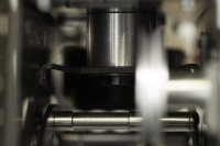
The images illustrate approximately: Step 2, Step 5, and Step 1 and 6 together, respectively.
View attachment 18904View attachment 18903View attachment 18902


