Bartman
Welcome to MultiRotorForums.com!!
Hi everyone,
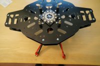
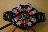
This project started a couple of months ago using a Mikrokopter XY8 frame set and an adapter board to mount the ESC's and the Hoverfly Pro flight control system. The nice folks at Hoverfly weren't exactly sure if their flight controller would be happy to find itself on my assymetrical coaxial quadcopter so the only way to find out for sure was to build it and have a go at flying it. It flew very well so the next step was to begin redesigning the frame plates specifically for mounting the Hoverfly Pro system.
It's not such a big challenge to put four holes in the right spots for a board to mount to so the goal of the build has become trying to design the neatest and lightest possible installation of a system that uses conventional ESC's and PWM control. To that end I'm experimenting with a few different power distribution ideas.
The first try at a power layout was with the PhotoShip One power board. All in all it's a neat board and has good size solder pads and an open layout. The problem I had with it though was that the pads are oriented +/- on two sides and -/+ on the other two sides. All of the ESC's have the positive on the left and the negative power wire on the right side. On the two sides where the pads match that layout, the wires fell into place well enough. On the other two sides though, the wires got messy as they had to criss-cross and I needed to leave a lot more wire on the ESC's to be able to maneuver them into place. I emailed DJ about the layout to ask if he had ever considered matching the pad layout to the ESC's on all four sides but I didn't get a reply.
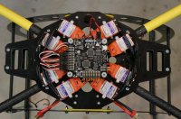
Going back to the internet to see what other boards could be used I decided to try the Voltair power board from MultiWiiCopter.com. The board is very compact, has sufficient solder pads for an oktokopter with dual batteries, and can be wired in a way that allows all four pairs of ESC's to be done uniformly on each of the four sides.
View attachment 4738
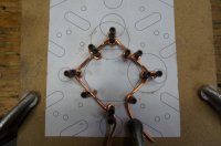
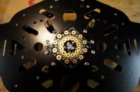
While trying to address the power needs of the motors I thought about modifying the Voltair board with 14AWG solid wire by bonding it to the underside of the solder pads to supplement the current carrying ability of the board. This made me think of another way to distribute power which involves winding a length of 10 AWG solid copper wire around posts that each represent the spot where I'd want to have an ESC wire attach to the power system. It was easy enough to make (the positive loop is shown) and I'll have to modify the positions of the loops a little but you can see the eight ESC attach points around the outside and the two positive battery attach points on the inside.
View attachment 4736View attachment 4737
I haven't decided yet which method I'll use but I think the Voltair board or my solid wire wrapped method will be minimal in terms of wire used to distribute the power.
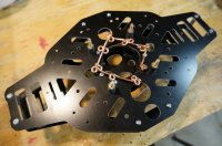
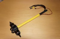
The wires for all eight motors will all come up from in between the frame plates through the triangular cut-outs on each side of the frame. THe motor attach points on the ESC's will be on the outside perimeter of the frame and I'll remove the wires that come soldered to the ESC and will solder the motor wires directly to the ESC's similar to how Mikrokopter attachments are made to the Bl's. The goal here is to make replacing motors or ESC's as simple as possible and I think to do that it helps to have open spots where wires are soldered using the most simple layout possible.
I'll be prepping the four arms tomorrow and will post pics tomorrow night of the arms with the motors and a better description of how the wires will be routed and attached.
THanks for reading,
Bart
This project started a couple of months ago using a Mikrokopter XY8 frame set and an adapter board to mount the ESC's and the Hoverfly Pro flight control system. The nice folks at Hoverfly weren't exactly sure if their flight controller would be happy to find itself on my assymetrical coaxial quadcopter so the only way to find out for sure was to build it and have a go at flying it. It flew very well so the next step was to begin redesigning the frame plates specifically for mounting the Hoverfly Pro system.
It's not such a big challenge to put four holes in the right spots for a board to mount to so the goal of the build has become trying to design the neatest and lightest possible installation of a system that uses conventional ESC's and PWM control. To that end I'm experimenting with a few different power distribution ideas.
The first try at a power layout was with the PhotoShip One power board. All in all it's a neat board and has good size solder pads and an open layout. The problem I had with it though was that the pads are oriented +/- on two sides and -/+ on the other two sides. All of the ESC's have the positive on the left and the negative power wire on the right side. On the two sides where the pads match that layout, the wires fell into place well enough. On the other two sides though, the wires got messy as they had to criss-cross and I needed to leave a lot more wire on the ESC's to be able to maneuver them into place. I emailed DJ about the layout to ask if he had ever considered matching the pad layout to the ESC's on all four sides but I didn't get a reply.
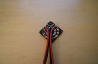
Going back to the internet to see what other boards could be used I decided to try the Voltair power board from MultiWiiCopter.com. The board is very compact, has sufficient solder pads for an oktokopter with dual batteries, and can be wired in a way that allows all four pairs of ESC's to be done uniformly on each of the four sides.
View attachment 4738
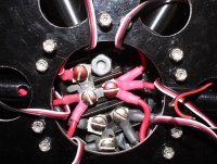
While trying to address the power needs of the motors I thought about modifying the Voltair board with 14AWG solid wire by bonding it to the underside of the solder pads to supplement the current carrying ability of the board. This made me think of another way to distribute power which involves winding a length of 10 AWG solid copper wire around posts that each represent the spot where I'd want to have an ESC wire attach to the power system. It was easy enough to make (the positive loop is shown) and I'll have to modify the positions of the loops a little but you can see the eight ESC attach points around the outside and the two positive battery attach points on the inside.
View attachment 4736View attachment 4737
I haven't decided yet which method I'll use but I think the Voltair board or my solid wire wrapped method will be minimal in terms of wire used to distribute the power.
The wires for all eight motors will all come up from in between the frame plates through the triangular cut-outs on each side of the frame. THe motor attach points on the ESC's will be on the outside perimeter of the frame and I'll remove the wires that come soldered to the ESC and will solder the motor wires directly to the ESC's similar to how Mikrokopter attachments are made to the Bl's. The goal here is to make replacing motors or ESC's as simple as possible and I think to do that it helps to have open spots where wires are soldered using the most simple layout possible.
I'll be prepping the four arms tomorrow and will post pics tomorrow night of the arms with the motors and a better description of how the wires will be routed and attached.
THanks for reading,
Bart