Mikrokopter Building Hexa XL dis board

Droider

Drone Enthusiast
After failing on my first attempt to build a error free Hexa XL board I am about to statrt a new one.

Can some one tell me the exact resistances to be expected between + & - on a hexa xl distribution board when it is fully built up with 6 BL2's

Also the resistances between C & D and + & -

Is there a wiki anywhere other than the hexa xl build wiki.

Can the Distribution board be tested for 12c errors as it is built..

Stage one

solder molex on board.

Stage 2

Test board for 12c continuity then check in MKtolls that there is no 12 error

Stage 3

Fit first BL test for shorts and continued continuity through 12c circuits, check in MKtool for error free 12c and recognition of first BL

Anyone??

Dave

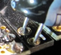
I thought I was super super precise taking my time with the last build but I think there was a fault with the board.. below build pictures

asset.php


asset.php


Droider

Drone Enthusiast
Dave, did you purchase a current limiting power supply yet?

Crash can you post a link to one..I have begun to set up my testing rig which I will post pics of when its ready. that would be a good addition

DAve
 

Droider

Drone Enthusiast
So..

I took everything apart had to cut up the distribution board to get all the bl's off. This is something to think about if you go for the new XL hexa distribution board. Because of the way you add the BL's its virtually impossible to remove them after soldering them up. I am also concerned about the possibility of the solder and flux running by capillary action where the board is sandwiched together. This can be minimised by soldering the caps and C/D links into the board before attaching the BL to the board.
 

Droider

Drone Enthusiast
After a total rebuild taking the greatest of care I still have exactly the same fault. Grrrrr..

The MKtools must be saying something by the following

In NAV control pain all status lights are green..

In FC pain NAV MAG are green BL red FC flashing red green..

This must tell you something...

DAve
 

DucktileMedia

Drone Enthusiast
I am curious, when you incur a serious problem like this, what happens when you ask Mikrokopter directly? Just wondering how easy it is to get info from the horses mouth.
 

Bartman

Welcome to MultiRotorForums.com!!
hmmmm, we're lucky in that we have a handful of guys with enough experience flying MK's to answer most questions. but to answer your question, I'd guess if your problem is serious enough and you have the patience to work within the challenges of the german forums, then you could probably expect to have one of the MK guys address your problem.
bart
 

Crash

Defies Psychics
Crash can you post a link to one..I have begun to set up my testing rig which I will post pics of when its ready. that would be a good addition

DAve
I use one like this (HY1803DL):
http://shop.ebay.com/i.html?_nkw=hy...y1803dl&_osacat=0&_trksid=p3286.c0.m270.l1313

It really does come in handy for many things from MKs to testing cameras, simulating low voltage, etc.

If you were to use it to charge batteries though it will get very hot. I ended up tapping into a 5V line in the box and run a computer 12V fan on the heatsink. It's very quiet and keeps the heat down.

For pulling apart distribution boards, this would be invaluable: http://cgi.ebay.com/808-KIT-808-KIT...493?pt=LH_DefaultDomain_0&hash=item230a84107d

It's pricey but it sucks the solder out of through holes like a pro. ;)
Solder wick and ChipQuik solder would work also.


Free samples: http://www.chipquikinc.com/free.html
 
Last edited by a moderator:


Crash

Defies Psychics
After a total rebuild taking the greatest of care I still have exactly the same fault. Grrrrr..

The MKtools must be saying something by the following

In NAV control pain all status lights are green..

In FC pain NAV MAG are green BL red FC flashing red green..

This must tell you something...

DAve
Pull off the navi and tuck it away until you get the FC working with the ESCs.

The important thing on the distribution board is that you need a lot of heat and fast heat transfer especially on the negative side. The solder has to run all the way through the holes. It will not build up between the boards unless it has metal to follow.

The joints should not look like the pic below. Take some pics and maybe someone will see something.
 

Attachments

  • screenshot.251.jpg
    screenshot.251.jpg
    12.4 KB · Views: 165
  • screenshot.310.jpg
    screenshot.310.jpg
    74.9 KB · Views: 191


tucker

Member
Dave, any update on your board? I'm following closely since I've just assembled my new Hexa XL db and will test it shortly. In the past I've always had them built by the shop but this time it's from scratch. I'm going to run 9v on my power supply and we'll see what happens. I don't think I can do much (any) damage if I use 9v? Not sure.

For desoldering the BL's I bought a Hakko 808 kit. Made the job of removing them sooo much easier. Would highly recommend one of those!!!
 

Dave -

I just rebuilt a HexaXL Distro Board myself. For de-soldering the BL's from my "first try", I started by just clipping the caps all off. I replaced them all with new ones from Mouser for about $8.

Then, with a cheap, bulb-based solder-sucker from Radio Shack (here in the US) I sucked out as much solder as I could from the connections. Then with lots of liquid flux, lots of heat, a quick solder hand, and lots of patience I would remove the jumpers that held the C and D end onto the board. Once that was free from the board, I was able to apply pressure to one side of the BL or the other as I repeated the procedure for each of the two caps on each board.

Once I had them all off, I cleaned their through-holes again (with the solder sucker and lots of flux), and then I cleaned the flux with lots of toothbrush, q-tips and alcohol.

I just re-soldered the new distro board this past weekend. This time I took heed to the recommendations of "use lots of heat". I set my Weller WLC-100 at its maximm setting. And I fluxed everything. I always heard people say "use lots of flux" but I only recently learned that it is because it helps make the solder more "liquid" and less "gummy".

I thought it would be awesome if I could make solder flow all the way from one side of the BL, through the DB, and out the other side. I was not so lucky. Even this second time around, the whole time I was soldering I thought to myself how poorly designed the DB was. I based this assertion upon its difficulty in soldering, and also based upon its lack of documentation. I also based my opinion upon the fact that there IS a metal-to-metal connection between the BL and the DB that cannot possibly be soldered . . . unless you do not keep ample pressure between the BL and the DB while you are soldering the two together.

I used some clamps I had around, but if I were to ever do it again, I would strongly encourage some small, rubber-tipped hobby clamps -- at least two per BL -- be used while soldering.

I lucked out, and when I connected my SECOND completed ring to my FC, I had no i2c errors.

I'm not sure if this info will help you, but it might help others who are about to solder their DB's. My other advice to anyone thinking of soldering the HexaXL Distro Board (or any of the new XL Distro Boards) is: SERIOUSLY consider buying the Distro Board pre-soldered, especially if you are buying the BL 2.0's brand new at the same time. It is a true PITA to solder that DB, and you face a higher-than-average risk that you will have to spend an equal amount of money trying a 'second time' as you will spend paying your MK dealer to send you one that is already completed.

Droider - I can say that your build looks GREAT and I hope you get your errors sorted out. I really like your use of wire braid - it looks really clean and professional!

Good luck!
 

Droider

Drone Enthusiast
Thanks DB

I thought I was going crazy.. People on the german MK site seem to of lost interest in the issues I had. Ho Hum... nowt like learning the hard way.

I asked loads of questions and got a few helpful replied on the GMK forum but nothing about the status lights flashing in MK tools.

I gave up with the new board it is in my parts box waiting for me to get the inclination to try get it apart. Since then I bought the standard dis board and built it in a very regimented fashion. NO ERRORs and good solder flow through the board.

I have completed my rebuild and have done al my testing on my new test rig which has given me the confidence to go out and fly. I have done a couple of packs at hover in the garden and it seems much more stable than my old one with very smooth transitions.. BUT its windy and raining. grrrr!

I may have to go re read what Crash has posted about the desolder sticks and go put the board apart!

Ill post some pics up

Dave
 

Bartman

Welcome to MultiRotorForums.com!!
hmmm.....why didn't i read this sooner? i ordered an Okto XL DB and was going to break down my old board this week to salvage my eight 2.0 BL's.
maybe i'll just box up the BL's and the new board and ship it back to Quadrocopter.us

have you guys been putting the heat on one end and letting the solder flow to the heat? the solder will flow on its own toward the hottest spot and i'd think that this would help the solder get through the holes and complete the joint, no?
 

Droider

Drone Enthusiast
Bart.. when you get it you will see what we are talking about.. you cant get the heat on bothboards. I use a 80watt iron at 480ºc and theres no way it will heat both boards up because of the gap between them.

Dave
 

Droider

Drone Enthusiast
So I am just going through threads I have started that do not have an answer..

So what was the problem with my Hexa XL distribution board build?

Well I guess I was trying to be to careful soldering the 12c circuit. I have made up two since with 100% success but using a more aggressive approach to the soldering of the 12c components.. Hot iron with a big tip and hit it hard. Solder flows job done.

If any one wants to know my build /testing procedure give me a shout.

Dave
 

Top