Product Review...Ardupilot Mega 2.5 + Hexacrafters HC-650

J3Cub

Member
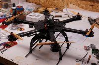
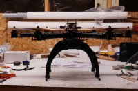
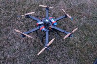
Hello and welcome to my review of the Ardupilot Mega 2.5 and Hexacrafter HC-650 hexacopter frame!
I would like to give a big thanks to Bart for giving me the opportunity to do this review for MultiRotorForums, 3D Robotics for the Ardupilot Mega 2.5 and Hexacrafter for the HC-650 frame.

The Ardupilot Mega 2.5 is a fully open source flight controller and autopilot system. Its features go far beyond that of basic radio controlled multicopters on the market today. The Apm2.5 offers position hold,fully autonomous flight, including waypoints, mission planning and telemetry with the use of GPS and independent telemetry radios.
Being an open source flight controller, the Apm2.5 doesn’t come with a typical instruction manual. The Arducopter Wiki is used as a guide and a tool for setup and tuning of the Apm2.5. This page will be cited throughout the review. http://code.google.com/p/arducopter/wiki/ArduCopter
The Apm2.5 is a very affordable option considering its extensive autonomous functions. It can be purchased here at 3D Robotics. http://store.3drobotics.com/products/apm-2-5-kit

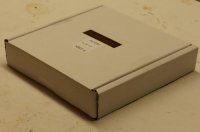
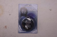
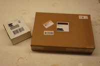
The Apm2.5 comes in a relatively small box. (seen on the left)
View attachment 11681
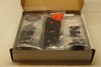
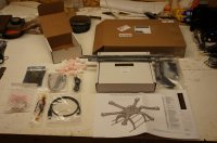
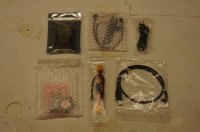
All of the components come neatly wrapped within the foam peanut filled box.
View attachment 11682View attachment 11683
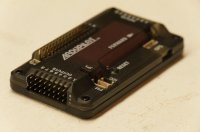
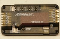
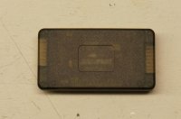
I am very impressed by the controller so far! The plastic case looks very nice and provides labels for each port. It feels solid and should do a good job of protecting the internal electronics.
View attachment 11685View attachment 11684View attachment 11686
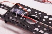
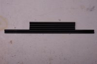
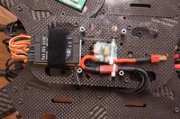
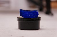
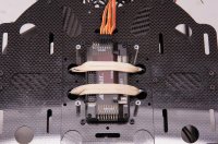
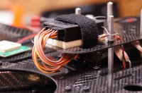
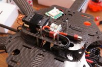
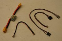
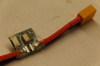
The Apm2.5 comes with a module that supplies power to the board. This ensures steady power along with adding the benefit of current and voltage telemetry (if telemetry radios are used).
View attachment 11689View attachment 11690
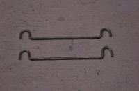
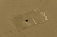
If the power module is being used inplace of power from the esc’s, this included jumper must be installed.
View attachment 11687
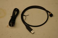
A usb cable is provided to connect the Apm2.5 to the mission planner, once installed on your computer. (left) The second usb cable is used to connect the 3DR telemetry receiver to your computer.(right)
View attachment 11688
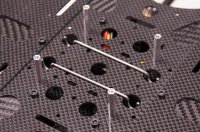
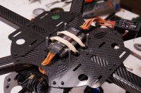
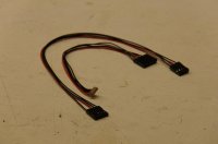
These cables are used to connect the telemetry transmitter to the Apm2.5.
View attachment 11691
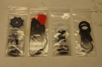
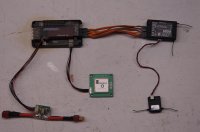
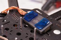
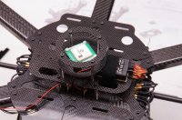
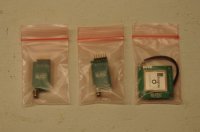
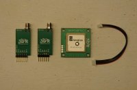
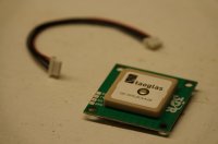
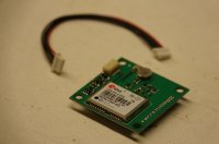
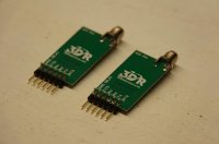
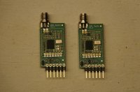
Pictured are the two, 915mhz telemetry radios along side the uBlox (upgraded) gps. The two telemetry radios are nicely protected by a plastic sleeve.
View attachment 11692View attachment 11694View attachment 11695View attachment 11696View attachment 11697View attachment 11698
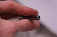
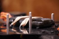
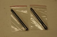
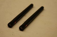
Two standard whip antennas are included. Nice and compact!
View attachment 11693View attachment 11699


Attachments

  • DSC01535.jpg
    DSC01535.jpg
    142.4 KB · Views: 686
  • DSC01537.jpg
    DSC01537.jpg
    139.1 KB · Views: 582
  • DSC01542.jpg
    DSC01542.jpg
    139.5 KB · Views: 567
  • DSC01548.jpg
    DSC01548.jpg
    127.9 KB · Views: 730
  • DSC01551.jpg
    DSC01551.jpg
    147.6 KB · Views: 739
  • DSC01554.jpg
    DSC01554.jpg
    142.6 KB · Views: 679
  • DSC01556.jpg
    DSC01556.jpg
    135.2 KB · Views: 566
  • DSC01562.jpg
    DSC01562.jpg
    131.4 KB · Views: 569
  • DSC01576.jpg
    DSC01576.jpg
    135.2 KB · Views: 572
  • DSC01585.jpg
    DSC01585.jpg
    136.6 KB · Views: 554
  • DSC01592.jpg
    DSC01592.jpg
    133.1 KB · Views: 553
  • DSC01597.jpg
    DSC01597.jpg
    129.1 KB · Views: 543
  • DSC01600.jpg
    DSC01600.jpg
    131.2 KB · Views: 566
  • DSC01602.jpg
    DSC01602.jpg
    133.9 KB · Views: 565
  • DSC01607.jpg
    DSC01607.jpg
    127.2 KB · Views: 571
  • DSC01614.jpg
    DSC01614.jpg
    125.9 KB · Views: 538
  • DSC01620.jpg
    DSC01620.jpg
    125 KB · Views: 520
  • DSC01627.jpg
    DSC01627.jpg
    137.9 KB · Views: 559
  • DSC01636.jpg
    DSC01636.jpg
    126.9 KB · Views: 568
Last edited by a moderator:

J3Cub

Member
The Hexacrafter HC-650 is a very high quality hexcopter frame. It can purchased here. http://www.hexacrafter.com/index.php?id_product=12&controller=product

As I unbox the HexCrafter HC-650, my first impression is “Wow!” The packaging is very neat and the quality of each component is definitely first class! The kit is sold just as the frame, with additional add-ons sold separately. In this case, I will be adding the load rail kit, frame style battery mounting kit, and medium length carbon fiber landing gear kit.
View attachment 11701View attachment 11702
All of the components are packed in bags within bags, which are then grouped according to their function and clearly labeled. There are many small screws and standoffs included in this kit, which are separated by size and kept in their respective bag. The quality of each part is very impressive.
View attachment 11703View attachment 11706
All of the carbon fiber looks very nicely finished.
View attachment 11704View attachment 11705
Next, I opened up the manual, which surely didn’t fail to impress! The front page has a detailed parts list showing each part number and a description. Every step of construction has a detailed ‘exploded view’ along with labels of each part used in that step. The format somewhat reminded me of a Lego manual. Towards the back of the manual, the steps for installing additional accessories, like load rails, battery mounts and landing gear, are also included.
View attachment 11707View attachment 11708
I began the build by first reading through the manual. Step one begins by preparing each of the 6 arms and motor mounts, while step two prepares the center hub. Although it was very clear where each screw and standoff went in step one and two, I was a bit confused when I flipped the page to step three, which showed the connection of the arms to the center hub. At this point, I pulled up the hexacrafters website and went directly to the assembly videos tab. I soon found that the videos were extremely helpful and immediately answered my question. As Andrew explained in the videos, each screw and standoff were to be applied with only finger tightness. This is done so that the screws on one side of the arm can be later removed, with the opposing screws keeping the standoffs within each arm aligned, so that the arm can be connected to the center hub. It did take a good amount of time to repeat this process; however, it was much easier than trying to hold the standoffs aligned within the arm, while also aligning the center hub. I would definitely recommend the use of both the instruction manual and the assembly videos while assembling this kit.
View attachment 11711View attachment 11709View attachment 11710View attachment 11712
This method, described by Andrew, is used to install the motor mounts. The standoffs are installed first with finger tightness, then the screws are removed from one side at a time to add the top and bottom plate. At this point, it is important to make sure the motor mounts are properly aligned so that the mounting holes result in the motor wires facing towards the hollow arms.
View attachment 11713View attachment 11714View attachment 11715
After all of the arms were assembled and attached to the center hub, I began work on the power board.
View attachment 11716View attachment 11717
All six, 30 amp esc’s are mounted on this board, which is attached just below the center hub. I mounted each esc with two zip ties and a piece of furry Velcro just to add some cushion.
View attachment 11718View attachment 11719
The included power distribution board makes wiring all 6 esc’s simple and allows for a very neat installation.
View attachment 11720
In addition to soldering the esc’s to the distribution board, I added a main power lead (about a foot long for now) and two shorter deans pigtail wires. These will be used to power led’s, fpv, or a gimbal, if I decide to add one or more of those options.
View attachment 11722View attachment 11721
With all of the esc’s installed to the power board, I decided it was time to mount the motors to the frame. Although motor installation isn’t specifically mentioned in the manual, I figured it would be a good time as the next step connects the power board to the frame. I am using Avroto 2814 770kv motors for this hex. The motors can be installed on either side of the mounting plate. I chose the ‘recessed’ installation as it looked cleaner and created a lower profile.
View attachment 11725View attachment 11724
The mounting holes aligned perfectly and I simply applied 4 of the included 6 mm screws, along with a drop of Loctite, to each motor.
View attachment 11723
I pulled the wires through the arms with the help of an old wire pushrod, and routed them through the bottom center plate. I cut them to the appropriate length and soldered on bullet connectors before the power board was attached to the frame.
View attachment 14964View attachment 14965View attachment 14966
At this point, I found the hex
motor rotation diagram on the wiki page and carefully labeled each esc by its assigned number and rotation. I also put a small piece of masking tape on each esc cable and numbered each accordingly.
View attachment 14968
Next, I attached the power board to the frame with the appropriate standoffs, allowing enough space for the excess wiring and adequate airflow for cooling. As I connected the bullet connectors, I added a piece of shrink tubing over each connection. This will prevent the bullet connectors from coming apart and also insulate all of the exposed connections.
View attachment 14967View attachment 14969
With the power board in place, I added the top center plate. This required taking the top screws for all of the arms out, and replacing them with the top plate in place. During this process, I also installed the side by side battery mounts. These can either be mounted on top or on the bottom of the hex. I chose the top for easier access. The plates align with the holes for each arm, and mount with supplied longer screws. Also supplied are four velcro battery straps, that really do grip the batteries well.

At this point, most of the major contruction was done. Before moving any further, I now tightened every screw, from either side of the frame, to ensure I wouldn’t leave any at just hand tight.
View attachment 14976View attachment 14972
Next up was the landing gear. The exploded view in the manual made this process very simple. I started by bolting the front and rear assemblies together.

View attachment 14970View attachment 14974
Four shorter carbon tubes, two longer landing skid tubes, and the two load rails hold the front and back landing gear assemblies together. The four shorter tubes require you to epoxy a threaded aluminum insert into each end of the tube. For this, I used 5 minute epoxy and made sure the glue was completely set before I tightened a screw on them.
View attachment 14973View attachment 14975
The landing skids are simply held in place by rubber grommets. Once the whole assembly was completed, I removed the load rails from the power plate, slid on the landing gear, centered it, and reinstalled the load rails onto the hexcopter. With the hexcopter now on its feet, the landing gear felt quite rigid and very stable.
View attachment 14980View attachment 14981
Now it was time to add the flight controller, receiver, gps, and power module. The Arducopter board is mounted to the top center plate.(more on this in post 3) The HC-650 comes with two plate options for mounting additional electronics above the flight controller. One is circular and the other is rectangular. I very much preferred the rectangle option as it left more room for the side by side battery mounting and the receiver fit neatly with a Velcro strap.
View attachment 14978View attachment 14979View attachment 14977
The HC-650 has provisions for DJI WKM, DJI Naza, Hoverfly, Open Pilot and KK. With the Arducopter board not being on this list, I had to drill a few holes to make this work. The Arducopter board required the widest spaced holes for the standoffs in order to fit between them. However, the circle shaped plate was the only one to fit with the wider spaced holes. With my decision being to use the rectangle plate, I marked and drilled four holes in this plate so the standoffs would align.
View attachment 14982View attachment 14983
After this, I mounted the receiver and power unit on the plate, mounted the gps on the next level up, and installed the gps protection ring above the gps.
View attachment 14987View attachment 14984
The final step in construction of the frame was to add the Xoar 10x5 props. Now it finally looks like a hexcopter!
View attachment 14985View attachment 14986
 

Attachments

  • DSC01647.jpg
    DSC01647.jpg
    129.1 KB · Views: 585
  • DSC01653.jpg
    DSC01653.jpg
    127.9 KB · Views: 533
  • DSC01654.jpg
    DSC01654.jpg
    137.4 KB · Views: 527
  • DSC01765.jpg
    DSC01765.jpg
    123.2 KB · Views: 536
  • DSC01819.jpg
    DSC01819.jpg
    129.7 KB · Views: 527
  • Untitled-1.jpg
    Untitled-1.jpg
    135.6 KB · Views: 522
  • DSC01638.jpg
    DSC01638.jpg
    135.6 KB · Views: 509
  • DSC01641.jpg
    DSC01641.jpg
    130.7 KB · Views: 664
  • DSC01777.jpg
    DSC01777.jpg
    139.9 KB · Views: 505
  • DSC01786.jpg
    DSC01786.jpg
    130 KB · Views: 549
  • DSC01797.jpg
    DSC01797.jpg
    123.4 KB · Views: 528
  • DSC01817.jpg
    DSC01817.jpg
    140.4 KB · Views: 501
  • DSC01794.jpg
    DSC01794.jpg
    121.1 KB · Views: 627
  • DSC01801.jpg
    DSC01801.jpg
    123.4 KB · Views: 641
  • DSC01808.jpg
    DSC01808.jpg
    135.4 KB · Views: 626
  • DSC01826.jpg
    DSC01826.jpg
    137 KB · Views: 696
  • DSC01833.jpg
    DSC01833.jpg
    143.8 KB · Views: 535
  • DSC01864.jpg
    DSC01864.jpg
    122.3 KB · Views: 502
  • DSC01874.jpg
    DSC01874.jpg
    143.8 KB · Views: 516
  • DSC01772.jpg
    DSC01772.jpg
    127.5 KB · Views: 495
  • DSC01974.jpg
    DSC01974.jpg
    147.1 KB · Views: 511
  • DSC01975.jpg
    DSC01975.jpg
    141.4 KB · Views: 648
  • DSC01980.jpg
    DSC01980.jpg
    122.3 KB · Views: 641
  • DSC01984.jpg
    DSC01984.jpg
    127.9 KB · Views: 627
  • DSC01985.jpg
    DSC01985.jpg
    130.2 KB · Views: 610
Last edited by a moderator:

J3Cub

Member
As mentioned in post 2, this section will go into detail of installation and wiring of the Ardupilot Apm2.5 board.
View attachment 14988
As mentioned before, a few modifications were required to allow proper spacing with the use of the electronics plate that I preferred. With these modifications in place, I navigated the Ardupilot wiki to find the mounting section. The wiki stressed that the Apm2.5 is sensitive to vibrations and this needs to be accounted for in mounting the board. Three options were outlined in the wiki. One option suggested the use of vibration isolating gel along with rubber bands lightly stretched around the board. Another option involved removing the board from the case to access the holes on each corner of the board. Rubber o-rings were then used to suspend the board from each corner. Because I didn’t have any standoffs conveniently placed on the frame (and I also like the added protection of the plastic case), I decided to use the first option. Having had success with Moon Gel in mounting gopro’s, I took a trip to the local music store and bought some more.
View attachment 15003View attachment 14992
Two strips of moongel neatly fit on the front and rear side of the board.
View attachment 14993
Paying careful attention to the alignment of the ‘forward’ arrow on the board, I decided to use rubber bands to attach the board to the frame. To do this, I bent two pieces of wire in order to create two hooks on either side of the board. The wires were place on the underside of the top center plate, with the two hooks exposed from the top.
View attachment 14989View attachment 14990
Four rubber bands, doubled over, applied appropriate pressure to the board.
View attachment 14994View attachment 14995
Next, I pulled the wires from all six esc’s through the frame and connected them to the ‘outputs’ side of the board. I bundled the excess wire, applied a small ziptie, and hid it between the top and bottom center plate. Having labeled each wire previously, this went very quickly.
View attachment 14996
After I installed the electronics plate and receiver, I used 5 male to male extension wires to connect the board to the receiver. Channels 1-4 on the receiver connected to their appropriate ‘input’ port on the board. (Arrangement found here) This information was found in the wiki. The fifth extension was connected to Aux1 on the receiver and input 5 on the board. This channel isused for changing flight modes, so I assigned it to a three position switch on my transmitter. I mounted the remote receiver along the side of one of the arms.
View attachment 14997View attachment 14999
Next, I installed the power unit for the Apm2.5 on the electronics board. To do this, I pulled my power lead from the distribution board through the frame, cut it to the correct length, and soldered a deans plug to it. A separate, 6 strand wire from the power unit is connected to the Apm2.5 to supply steady power and allow the use of voltage and current telemetry. The power unit was installed with a few zip ties and positioned so that the input side could be easily accessed in order to connect the battery.
View attachment 15002
Finally, the gps was installed above the power unit with the gps plate and protection ring. I mounted the gps with a small piece of foam beneath it and a few zip ties on the four corners.
View attachment 15000View attachment 15001
 

Attachments

  • DSC01987.jpg
    DSC01987.jpg
    146.2 KB · Views: 645
  • DSC01992.jpg
    DSC01992.jpg
    140.8 KB · Views: 640
  • DSC02000.jpg
    DSC02000.jpg
    128.9 KB · Views: 634
  • DSC02004.jpg
    DSC02004.jpg
    130.8 KB · Views: 704
  • DSC02005.jpg
    DSC02005.jpg
    145.6 KB · Views: 585
  • DSC02095.jpg
    DSC02095.jpg
    146.7 KB · Views: 632
  • DSC01642.jpg
    DSC01642.jpg
    131.3 KB · Views: 720
  • DSC02090.jpg
    DSC02090.jpg
    144.9 KB · Views: 401
  • DSC02100.jpg
    DSC02100.jpg
    139.9 KB · Views: 636
  • DSC02169.jpg
    DSC02169.jpg
    141.8 KB · Views: 623
  • DSC02172.jpg
    DSC02172.jpg
    142.5 KB · Views: 602
  • DSC02178.jpg
    DSC02178.jpg
    142.1 KB · Views: 640
  • DSC02086.jpg
    DSC02086.jpg
    142.1 KB · Views: 610
  • DSC01764.jpg
    DSC01764.jpg
    119.2 KB · Views: 528
  • DSC02014.jpg
    DSC02014.jpg
    135.2 KB · Views: 528
  • DSC02081.jpg
    DSC02081.jpg
    135.7 KB · Views: 736
  • DSC02192.jpg
    DSC02192.jpg
    124.9 KB · Views: 548
  • DSC02198.jpg
    DSC02198.jpg
    143.4 KB · Views: 654
  • DSC02082.jpg
    DSC02082.jpg
    144.7 KB · Views: 665
  • DSC02083.jpg
    DSC02083.jpg
    150.2 KB · Views: 636
  • DSC02305.jpg
    DSC02305.jpg
    139.9 KB · Views: 658
  • DSC02315.jpg
    DSC02315.jpg
    142 KB · Views: 669
  • DSC02317.jpg
    DSC02317.jpg
    134.7 KB · Views: 645
  • DSC02322.jpg
    DSC02322.jpg
    153.2 KB · Views: 674
Last edited by a moderator:

J3Cub

Member
Calibrating the Ardupilot Apm2.5 can be intimidating at first, but was surprisingly easy with the use of the wiki. The first step is to install the flight planner software, which can be found on the wiki. Using the wiki as a step by step guide, I connected the Apm2.5 to my laptop. Unlike many other systems I’ve used, the Apm2.5 uses power from the laptop during setup. This made me feel very safe during setup, as I knew the motors couldn’t come alive without a lipo battery connected. Within the setup, I loaded the hexcopter firmware, calibrated the transmitter, set the stabilize, acro and loiter flight modes, and finally calibrated the accelerometers. The initial setup took about 10 minutes and included everything needed before the first test flight could be performed.
View attachment 11766View attachment 11767
For the first test flight, I brought the hexcopter to a large, open park on a calm day. Within the transmitter, I toned down the ailerons, elevator and rudder to 70% with 20% expo. The wiki strongly recommends flying, especially for the first flight, on stabilize mode. This means that both gyros and accelerometers are being used to bring the copter back to level.
View attachment 11769
Once I checked and double checked each aspect of the setup, I was ready for the first flight. I powered on the transmitter, plugged in the battery, and waited for the system to initialize. GPS lock came very quick, followed by the ‘ready’ light code from the board. I held low throttle and full right rudder to arm the board, which was indicated by a change in led’s on the board. I slowly advanced the throttle and let the hexcopter lift off the ground. In stabilize mode, almost no correction was needed to hold a hover. I was very impressed with this! As I got more comfortable, I moved into some slow forward flight. I quickly found that the default PID settings were a little aggressive for this size hexcopter. The copter oscillated and sort of wobbled in forward flight. The same effect was prevalent in acro mode, however, I felt that I had more control of the movements. I couldn’t wait to try loiter mode ,so I climbed to a safe altitude and switched into loiter. This was the most impressive part of the first flight! The hexcopter held its position perfectly, despite a light headwind.
View attachment 11771View attachment 11770


After the initial test flight, I knew I needed to make some fine tuning adjustments to the PID settings. There are a few different methods that all work systematically through the P, I and D settings. One option was to suspend the copter with strings through either the pitch or roll axis. With this method, you are able to simulate the copter actually flying, but in a very controlled environment.
View attachment 11768


Because I felt the HC650 was a little big for this method, I decided to use DaveC’s method, which was recommended by the wiki. In this method, you start with P, followed by D, P again, and finally I. Instead of tying down the copter, this method recommends that you create a jig, or very carefully hold the copter in your hand with proper face and hand protection. Again, I didn’t feel comfortable doing this with a larger copter, so I did a quick test flight each time I tweaked a parameter. This was much more time consuming, but I had a good feel for what each adjustment was doing.
After making a few small changes mainly to the P and D settings, I could feel the hexcopter becoming much more controllable and less wobbly. I could also feel a more noticeable difference between stabilize and acro mode. At this point, I could maintain a hover, forward flight and execute turns with no problems. The hexcopter still wobbles slightly in forward flight, which I am currently working on resolving.
 

Attachments

  • DSC02266.jpg
    DSC02266.jpg
    142.4 KB · Views: 665
  • DSC02272.jpg
    DSC02272.jpg
    129.7 KB · Views: 645
  • DSC02273.jpg
    DSC02273.jpg
    151.4 KB · Views: 685
  • DSC02276.jpg
    DSC02276.jpg
    129.6 KB · Views: 399
  • DSC02280.jpg
    DSC02280.jpg
    130.8 KB · Views: 673
  • DSC02285.jpg
    DSC02285.jpg
    145.3 KB · Views: 669
  • DSC02290.jpg
    DSC02290.jpg
    153.2 KB · Views: 656
  • DSC02291.jpg
    DSC02291.jpg
    138.7 KB · Views: 648
  • DSC02293.jpg
    DSC02293.jpg
    152.3 KB · Views: 692
  • DSC02301.jpg
    DSC02301.jpg
    140.7 KB · Views: 665
  • DSC02304.jpg
    DSC02304.jpg
    136.5 KB · Views: 746
  • DSC02307.jpg
    DSC02307.jpg
    132.2 KB · Views: 695
  • DSC02308.jpg
    DSC02308.jpg
    144.6 KB · Views: 666
  • DSC02321.jpg
    DSC02321.jpg
    149.2 KB · Views: 645
  • DSC02275.jpg
    DSC02275.jpg
    139.2 KB · Views: 680
  • 1.jpg
    1.jpg
    86.8 KB · Views: 714
  • 2.jpg
    2.jpg
    142.6 KB · Views: 647
  • 3.jpg
    3.jpg
    94.2 KB · Views: 636
  • DSC02326.jpg
    DSC02326.jpg
    155.8 KB · Views: 583
  • DSC02327.jpg
    DSC02327.jpg
    146.3 KB · Views: 628
  • DSC02328.jpg
    DSC02328.jpg
    141.5 KB · Views: 646
Last edited by a moderator:


Bartman

Welcome to MultiRotorForums.com!!
Thank you very much to Tucker for taking on this review assignment. I think he's done a fantastic job and has definitely raised the bar for future reviews!

He's graduating high school next month and has been working on getting college plans laid out while also packing chutes and editing video for the local skydiving operation. Lucky for us, he couldn't pass up the opportunity to get his hands on a new flight control system and frame to test out. At this point the whole system is flying but in need of further tweaking. Post #4 will get us into the flying and there will be an additional installment once he has the numbers in the firmware all settled out.

Great job Tucker!
 

This is perfect timing for me, as I finally stumbled on to the apm site, and I am considering this build. -- thanks so much and I am looking forward to the rest of your review!


SamaraMedia

Active Member
Nice job Tucker. Not that I need to delve into another controller but the AMP has me thinking, which can be trouble...
 

Hexacrafter

Manufacturer
Tucker,
Thank You for all of your hard work and the VERY comprehesive review of both the HexaCrafter HC-800 & Ardupilot Mega 2.5.
We hope you will enjoy many years use & flights with the airframe.
We have added the additional 4 holes in the Flight Electronics Plate that you have recommended in future kits. This should now allow seamless integration of the Ardupilot Mega 2.5 for those wishing to fly it.
Thanks Again.

Andrew


Bartman

Welcome to MultiRotorForums.com!!
Gmac,

Tucker started college this year so he hasn't been doing much RC flying. He hasn't been through here in a while so you might not get a response. Post in the forum for this controller and you should get what you're looking for.

Thanks!
Bart
 

Top