Need an engineers help on BL-Ctrl failure

Crash

Defies Psychics
I'm working on a bad MK BL-Ctrl that I believe caused another problem.

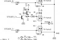
The schematic below is for the FET section. Can one of you electrical engineers tell me what would happen if R25 was to fail.

Kirk

Edit: I should have been more specific. It's a version 2 BL-Ctrl.

I know R25 will stop the FET from switching and stop the motor or greatly loose motor power. Luckily the craft wasn't airborn.

Will phase C then stay positive? How will that affect the motor windings. Where will the heat be generated on the circuit board?

As you guys can probably guess, I am getting at something. Hopefully I can get some confirmation of the after effects first.
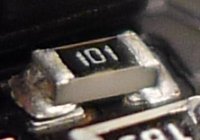
 

Attachments

  • screenshot.315.jpg
    screenshot.315.jpg
    55.7 KB · Views: 183
Last edited by a moderator:


matwelli

Member
If R25 Fails, the FET will not switch on, R24 will keep the FET off.

Phase C wont stay positive, it will only go Positive when the Fet above is turned on.

Howver, it will stop the motor turning, will act as if the motor has lost a winding, and cause a massive amount of current thru the other two phases, overheating and destroying either the motor windings or the FETS on Phase A or Phase B

Thats my take on it anyway


Crash

Defies Psychics
If R25 Fails, the FET will not switch on, R24 will keep the FET off.

Phase C wont stay positive, it will only go Positive when the Fet above is turned on.

Howver, it will stop the motor turning, will act as if the motor has lost a winding, and cause a massive amount of current thru the other two phases, overheating and destroying either the motor windings or the FETS on Phase A or Phase B

Thats my take on it anyway

Hmm, we finally got a good picture of the resistor.

View attachment 204

I had thought that the resistor was like that from the factory, but now I'm not so sure. Fox over in the other forum has seen heat cause that type of detachment.

Both C FETs are blown and there is what I believe to be signs of heat in the vicinity of that resistor. There are also two pairs of burnt windings. I'll have to check but I believe they go to the C line.
 

Attachments

  • screenshot.321.jpg
    screenshot.321.jpg
    27 KB · Views: 245

Bartman

Welcome to MultiRotorForums.com!!
Life was so much simpler when I was flying a Sig Kadet with a K&B .40 on it.
 

Bartman

Welcome to MultiRotorForums.com!!
If R25 Fails, the FET will not switch on, R24 will keep the FET off.

Phase C wont stay positive, it will only go Positive when the Fet above is turned on.

Howver, it will stop the motor turning, will act as if the motor has lost a winding, and cause a massive amount of current thru the other two phases, overheating and destroying either the motor windings or the FETS on Phase A or Phase B

Thats my take on it anyway

Confess! What's your background Mat? Or is it Holger?
 

matwelli

Member
sorry bart - not sure on the "holger" reference.

Electric technician for 4 years, instrument tech for 13 years, did 75% of an engineering certificate in electronics, but life got in the way and never finished
 

matwelli

Member
I wonder if its the other way around,

The failure may have been in the control circuit feeding the fets (lost sync or other issue), and when the fets cooked up, the heat was enough to lift R25's solder pad, which may not have been the best to start with.

If R25 had gotten hot (unlikely) it would look very chared, before the solder let go

Whats your thoughts Crash ?

Hmm, we finally got a good picture of the resistor.

View attachment 341

I had thought that the resistor was like that from the factory, but now I'm not so sure. Fox over in the other forum has seen heat cause that type of detachment.

Both C FETs are blown and there is what I believe to be signs of heat in the vicinity of that resistor. There are also two pairs of burnt windings. I'll have to check but I believe they go to the C line.
 

Bartman

Welcome to MultiRotorForums.com!!
sorry bart - not sure on the "holger" reference.

Electric technician for 4 years, instrument tech for 13 years, did 75% of an engineering certificate in electronics, but life got in the way and never finished

i was only kidding about the holger comment as if maybe you are holger in disguise. holger as in the MK guy named Holger.


Crash

Defies Psychics
I wonder if its the other way around,

The failure may have been in the control circuit feeding the fets (lost sync or other issue), and when the fets cooked up, the heat was enough to lift R25's solder pad, which may not have been the best to start with.

If R25 had gotten hot (unlikely) it would look very chared, before the solder let go

Whats your thoughts Crash ?

R25 or it's trace can't carry enough current to get that hot by itself. However if I'm not mistaken, these are 4 layer boards. I have seen the shunts on the V1.2 boards cook, but there is no visible shunt on the V2 boards. I have wondered if the shunt or something else that carries a lot of current is on one of the middle two layers. I don't have those new boards so I can't take my time and inspect one.

This motor did work for a couple short flights. I'm not sure what that means other than the BL-CTRL was working and the motor was working - until it stopped working in a flash of smoke.

I suppose it's possible that the motor windings had a slight flaw that cascaded until it shorted the entire phase and then caused enough current to fry the FETs, heat up some inside trace, and melt the solder on a resistor just above it that is also on the same phase.

I still can't understand how the solder could pull away from the pad so cleanly. I saw it through a 30x microscope. The surface tension of the solder should have held it in place. If I'm not mistaken, they oven solder double sided boards with the parts held on the bottom just by the melted solder.

Incidentally, of the other 7 motors on this bird, there was another that did not have a phase fully wired.

I dunno. Monday motors?
 

Top