KDE Direct
KDE Direct, LLC.
Hey Guys,
With all the range of equipment in the market, making all systems compatible is near impossible as a plug-and-play offering between ESCs/Brushless Motors and Flight Controllers.
The KDE Direct XF ESCs are high-quality devices and as such, institute true bi-directional OPTO-isolation for the three-wire RX or Flight Controller control lead. Why did we add this circuitry? The OPTO-isolation provides true isolation of the ESC electronics to the flight controller (and video equipment), preventing any passage of RF Noise or Voltage-Ripples, that can cause all kinds of issues with the overall electronics. One of the key features for the smoothness and accuracy of the KDE Direct XF ESCs is the electrical isolation of the circuits, allowing the ESC and Flight Controller to remain electrically "clean" from each other and not transmit electrical noise. Other high-end systems employ the same methodology in commercial/industrial applications.
For the DJI equipment, there are no compatibility issues and the two systems work in great harmony. DJI takes care of the proper throttle range and radio calibration in the software (done during calibration of the stick endpoints), so the XF ESCs are simple plug-and-play devices.
For the X-Aircraft equipment, no compatibility issues - only requirement is for the radio to be properly programmed to the controller. The KDE Direct XF ESCs are pre-calibrated at our factory to the Futaba standard of 1100us to 1900us, centered around a 1520us pulse width. Why do we factory-calibrate the ESCs? This allows for the ESC to have a truly linear-throttle curve from arming (1100us) all the way up to full-power (1900us), and ALL ESCs remain consistent out of the box. One of the problems with calibrating ESCs to various radios is the loss of this control and consistency between ESCs, and this can negatively affect flight performance when looking for the best setup for multi-rotors. It is important to calibrate your radio (TX) throttle end-points (for radios other than Futaba/JR standards) to this range for the best operation, and the SuperX is then an excellent match to the XF ESCs and used worldwide.
For the 3D Robotics Pixhawk equipment, there is a hardware incompatibility of the Pixhawk to true, high-quality OPTO-isolated ESC circuitry. For OPTO-isolated ESC circuitry, the positive/negative control loop of the system must occur at each ESC port of the flight-controller, so that the circuitry is properly powered and kept separate from the full system. The Pixhawk hardware does not provide this, and rather, completes this loop through the ESC itself, grounding all ESCs to the central ground of the Power-Module. While this will work, it can introduce significant noise to the full system, as all ESCs are tied together to a central ground. For ESCs that are NOT OPTO-isolated, this will work and the ESCs will arm, but RF and electrical noise will pass through the system and can lead to instability issues or video noise.
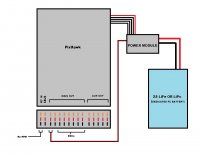
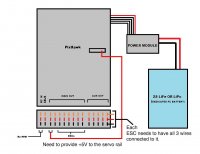
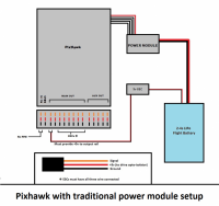
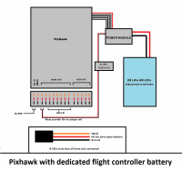
To solve this, customers have provided great insight to the hardware and the current solution (special thanks to Rob, Freddie, and Quoc for their insight), which is to introduce a grounding-loop to the system. This allows the OPTO-isolated ESC circuitry to properly function, and the overall system will work excellent for flight. This is created by adding a negative and positive loop from the Power-Module to the Pixhawk, using one of the open ports of the "Main Out" section. In this regard, adding a jumper from the Power-Module direct to the "Main Out" section will provide the negative-ground loop - then all ESCs will properly arm. Please see the attached image to help explain the proper jumper arrangement.
Same as the X-Aircraft equipment, the radio and software needs to be calibrated to the 1100us to 1900us range for proper operation. Make sure, in the 3D Robotics Mission Planner radio calibration, that your transmitter Throttle PPM range is programmed to 1100-1900. Until Pixhawk is armed, it will output <900us to the ESCs, and the ESCs will not arm until the onboard arming button is pushed. When the button is pushed, Pixhawk will output just below 0% throttle, allowing the XF ESCS to arm and report the cell count. Finally, when armed from the radio (TX), the controller jumps up to the selectable idle speed and the system is ready for flight.
We hope this all helps to clarify compatibility with various systems and we will continue to release information for others as the technology progresses.
Thanks,
Patrick Koegler
Owner, KDE Direct
Attachments
Last edited by a moderator:


